Check it out! An dont laugh, it is my first time on camera 🙂 Leave a comment if you stop by!
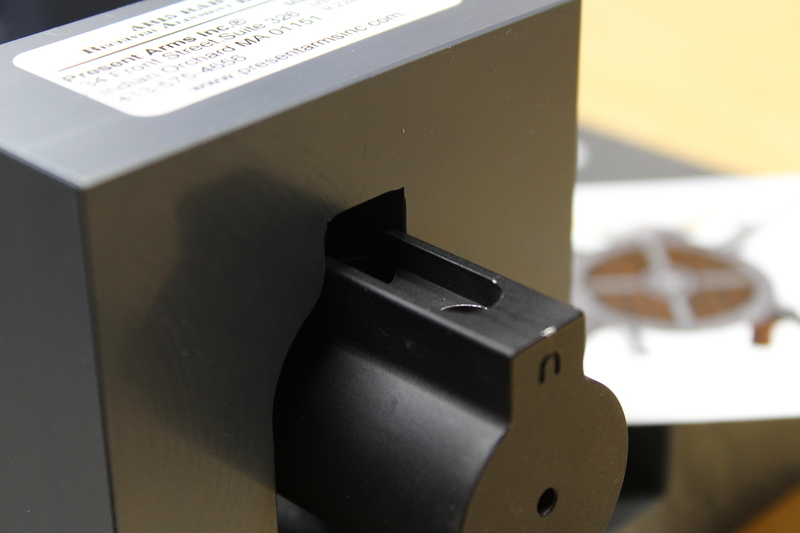
We are Veteran family owned small business; Wife and Kids
We do 3D printing of mostly Glock / Modern Sport Rifle items
Some of the items we make are:
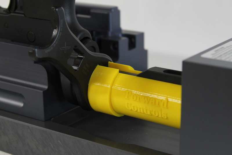
Glock Performance trigger tool
Glock Pins
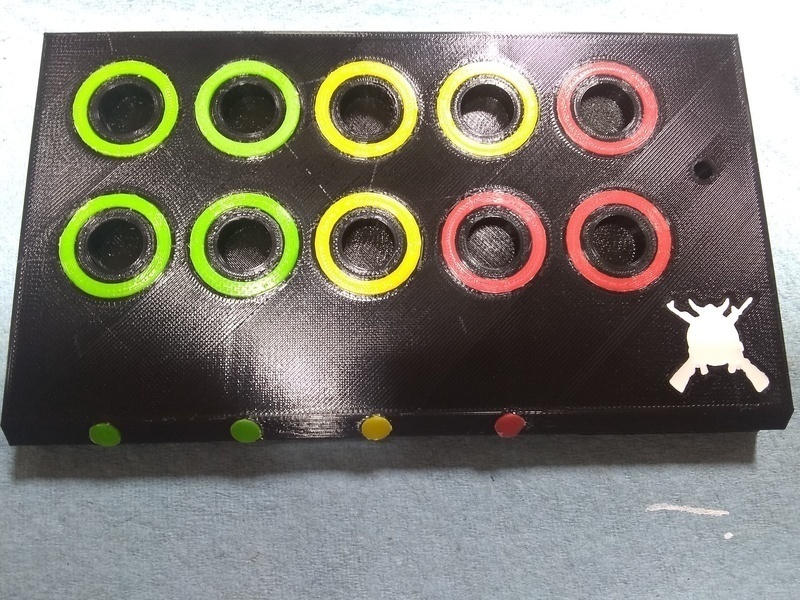
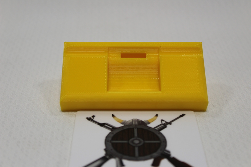
Glock Parts Tray
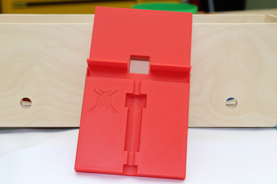
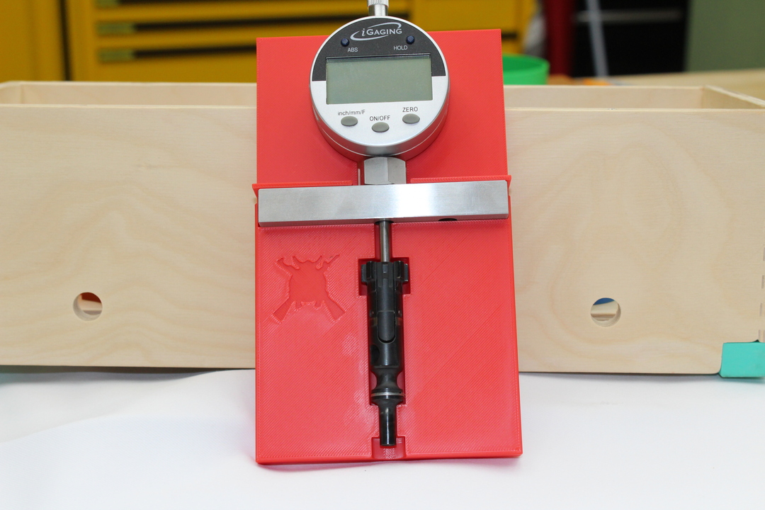
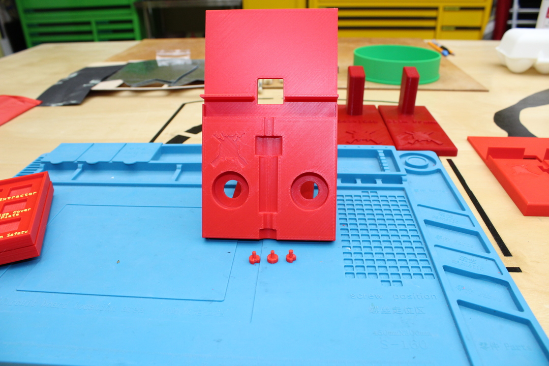
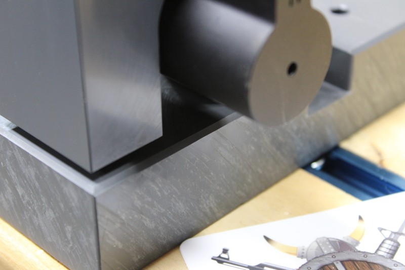
GlockSmith Block
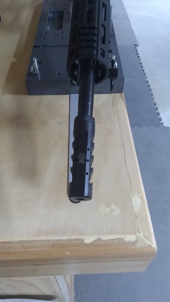
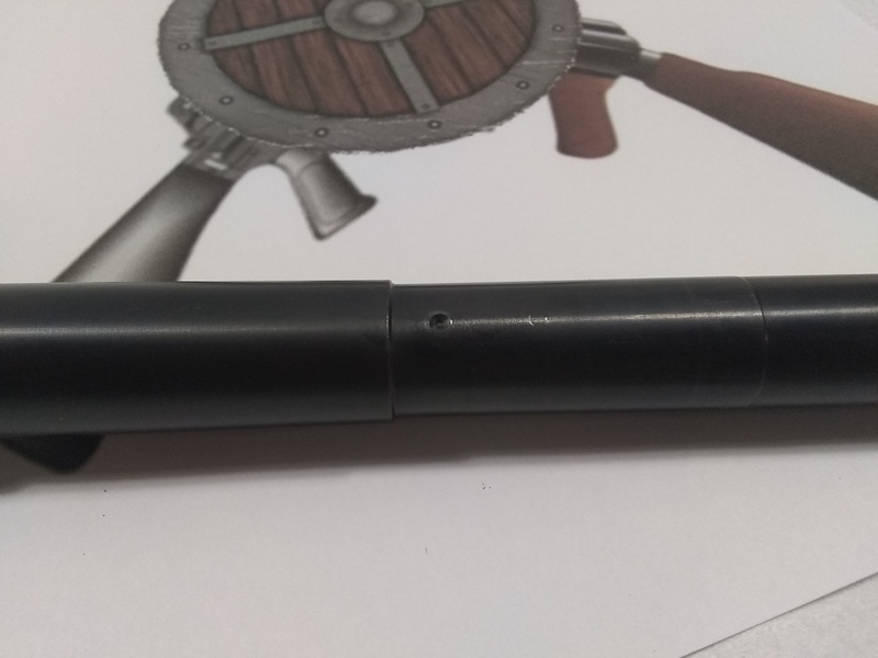
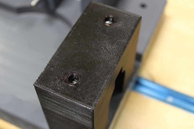
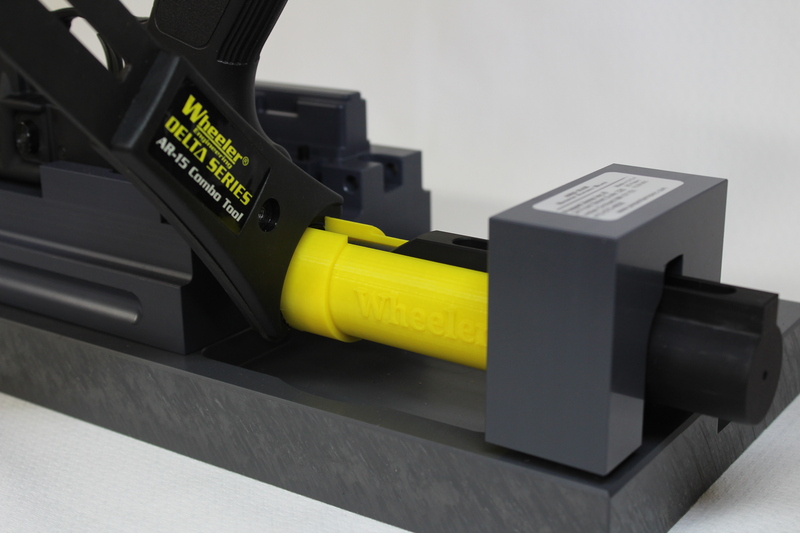
Vise and Slide Blocks
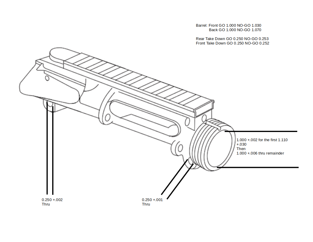
We also make AR-10, AR-15, AK47 and 74 Vise blocks with more for both coming down the line.
We are going to create a series of videos on on all the items we sell. We hope this will help you to decide to purchase our products as well as answer questions before, during and after purchase.
We stand 100% behind our products. All our Red, Base colored items are printed with PCTG filament sourced right here in the United States of America! We can not make that promise if you want a specific color or filament we cant find.
On that note, we will customize color at no additions cost as long as we have it on hand. It might take us a bit longer to get out depending on the print.
If you want custom logo and/or text get in touch with us BEFORE you order to work out any details.
We went to Shopify because hopefully they don’t drop our products for policy violations. Etsy would just randomly drop items and eBay does not seem to like rifle stuff.
All our reviews are on ebay right now, I will put a link below if you want to check them out. https://feedback.ebay.com/fdbk/feedback_profile/fishhorncreation