Hit us up with comments or requestsAll Documents posted on this site are for informational use only. If you make ANY modifications to your Weapons based on this site, you do at your own risk! If done incorrectly, you can render you weapon unsafe and / or unusable.
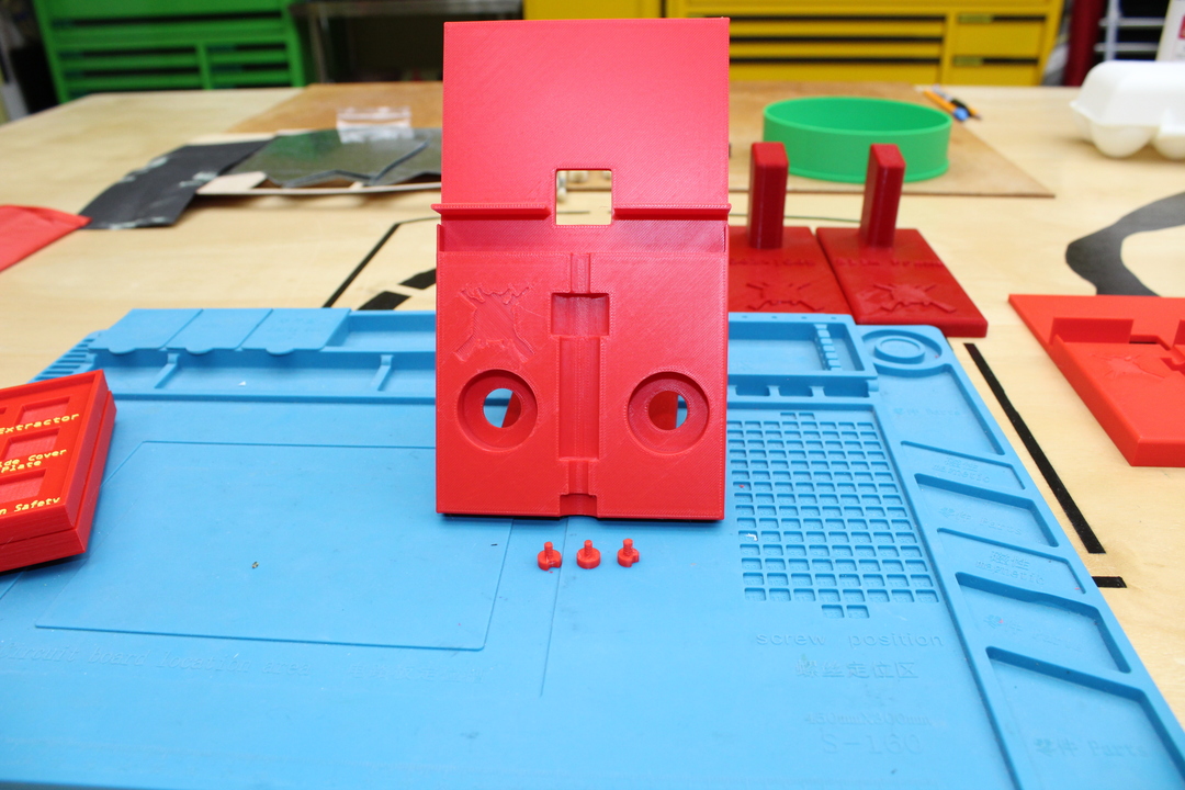
I started working on a holder for the AR15 Bolt Carrier Group (BCG) Pins. The idea came from School of the American Rifle. I wanted to be able to remove the pins if needed. I also did not want to paint my pins for GO / Warn / NO-GO. Here is what I came up with.
Got everything printed up in the right colors and numbers. You can switch it up how ever you like:
Everything printed up in the right colors
Then I put it all together. I had to cleanup everything with sandpaper, file and an Exacto knife. With a little help from a small nylon hammer. I got everything in place. Even tried a little infill using model paint.
AR-15 BCG Test Pin Tray Put Together
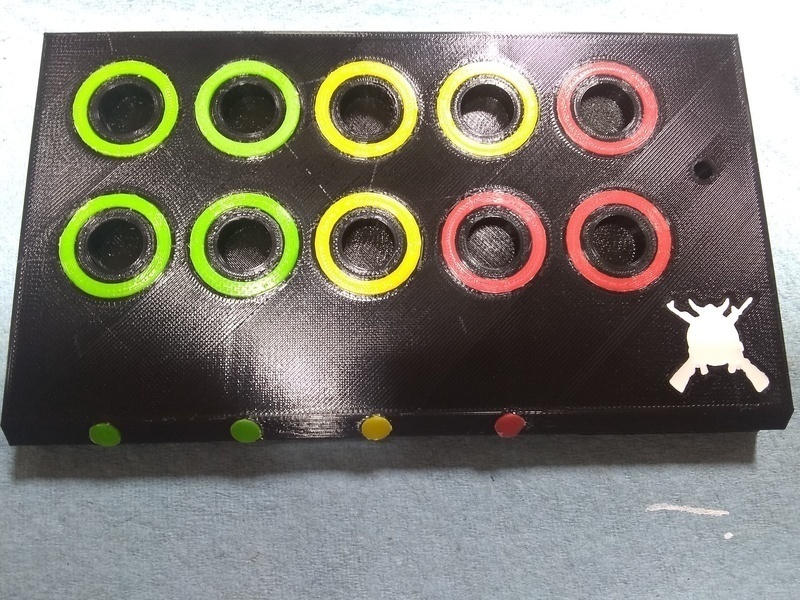
Added all the pins in:
AR-15 BCG Test Pin Tray All together
So far it is working out pretty good. It is another tool in the toolbox when troubleshooting AR15 Bolt Carrier Groups (BCG) The pin sizes are born out of the data I pulled from my research HERE.
All Documents posted on this site are for informational use only. If you make ANY modifications to your Weapons based on this site, you do at your own risk! If done incorrectly, you can render you weapon unsafe and / or unusable.
All Documents posted on this site are for informational use only. If you make ANY modifications to your Weapons based on this site, you do at your own risk! If done incorrectly, you can render you weapon unsafe and / or unusable.
All Documents posted on this site are for informational use only. If you make ANY modifications to your Weapons based on this site, you do at your own risk! If done incorrectly, you can render you weapon unsafe and / or unusable.
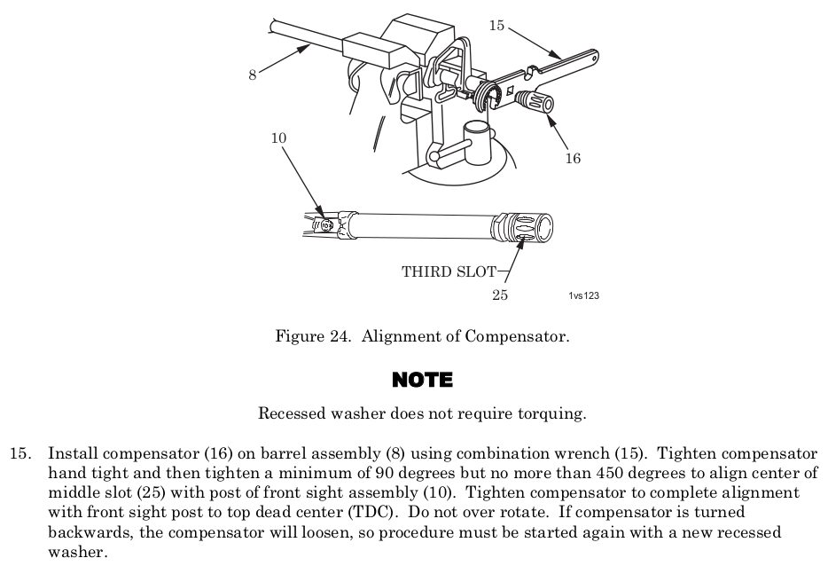
AR Compensator (Flash hider) No Torque, timing value with the procedure in the Army TM. Hand tight and then tighten a minimum of 90 degrees but no more than 450 degrees to timing. Don’t over tighten, don’t loosen.
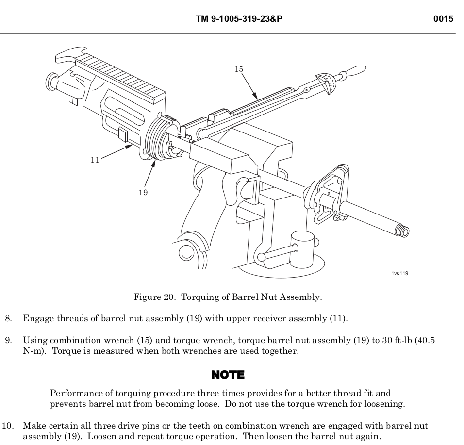
AR Barrel Nut 30 Ft. lbs. Minimum, not to exceed 80 Ft. Lbs. to align the next slot in the barrel nut. The 80 Ft. Lbs is not stated in the TM, but I don’t know how you would line up the gas tube, without going over 30 Ft. Lbs. Unless you use shims. I don’t think most folks will have any laying around. This torque spec is common across the community and internet.
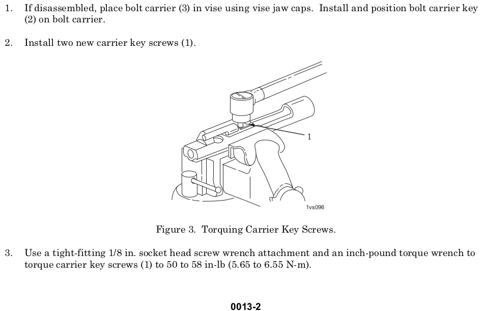
AR Carrier Key Screws 50-58 INCH pounds torque
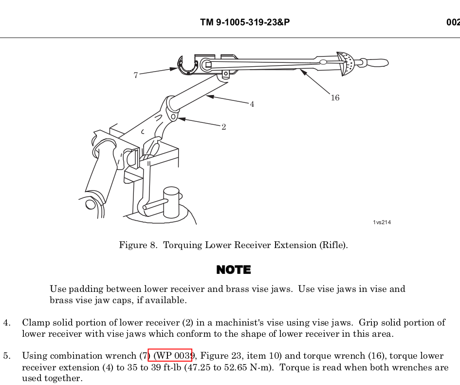
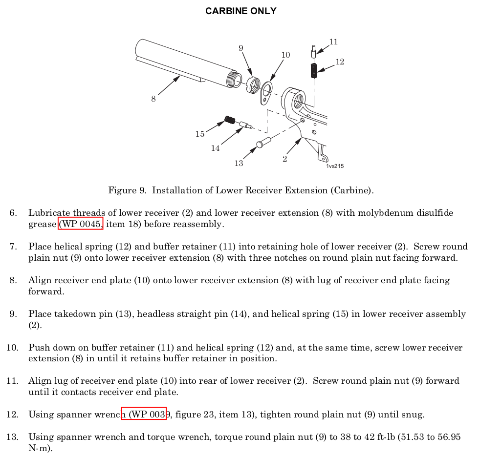
AR Lower Receiver Extension (Buffer Tube/Castle Nut) 40 Ft. lbs for both Rifle and Carbine.
M-LOK Accessories:
For attaching metal accessories to metal hand guards: 35 in/lbs
For attaching polymer or metal accessories to polymer hand guards: 15 in/lbs
For attaching polymer accessories to metal hand guards: 15 in/lbs
The installation torque values are not minimums, they are recommended limits. The nylon patch compound may slightly affect the torque reading if using an in/lb torque wrench.
Using a small hex wrench should prevent over-tightening. Remember that the recoil lugs are doing most of the work, and excessive torque on the nuts is not required
My Comments:
The rest of the items in the research below I could not find in the Army TM, manufacture website or in common reference. Until I can find it, I am going with ‘tight’ and the appropriate thread lockers. ‘Tight’ might be the values listed.
I am not saying that the info below is wrong or bad. I could not readily verify it. The above is what I will use, at the end of the day I am responsible for my decisions and you are responsible for yours.
########### RESEARCH ITEMS BELOW ###########
AR Compensator (Flash hider), 15-20 Ft. Lbs. Torque *1
AR Compensator (Flash hider) *3 (No Torque, timing value)
Army TM Flash Hider
AR Handguard Screws, 20-30 inch pounds torque *1
AR Gas Block Set Screws, 25-30 inch pounds torque *1
AR Barrel Nut, 30 Ft. lbs. Minimum, not to exceed 80 Ft. Lbs. to align the next slot in the barrel nut. *1 *5
AR Barrel Nut, 30 Ft. lbs. *3 (I cant find the 80 Ft. Lbs. In the TM)
Army TM Barrel Nut
AR Carrier Key Screws, 50-58 INCH pounds torque *1 *2 *3
Army TM Gas Key
AR Grip Screw, 15-20 inch pounds torque *1
AR Lower Receiver Extension (Buffer Tube/Castle Nut)
Rifle: 35-39 Ft. Lbs. *1 *3
Army TM Lower Receiver Rifle
Carbine: 38-42 foot pounds *1 *3
Army TM Lower Receiver Carbine
M-LOK Accessories: *4
For attaching metal accessories to metal hand guards: 35 in/lbs
For attaching polymer or metal accessories to polymer hand guards: 15 in/lbs
For attaching polymer accessories to metal hand guards: 15 in/lbs
The installation torque values are not minimums, they are recommended limits. The nylon patch compound may slightly affect the torque reading if using an in/lb torque wrench.
Using a small hex wrench should prevent over-tightening. Remember that the recoil lugs are doing most of the work, and excessive torque on the nuts is not required
All Documents posted on this site are for informational use only. If you make ANY modifications to your Weapons based on this site, you do at your own risk! If done incorrectly, you can render you weapon unsafe and / or unusable.
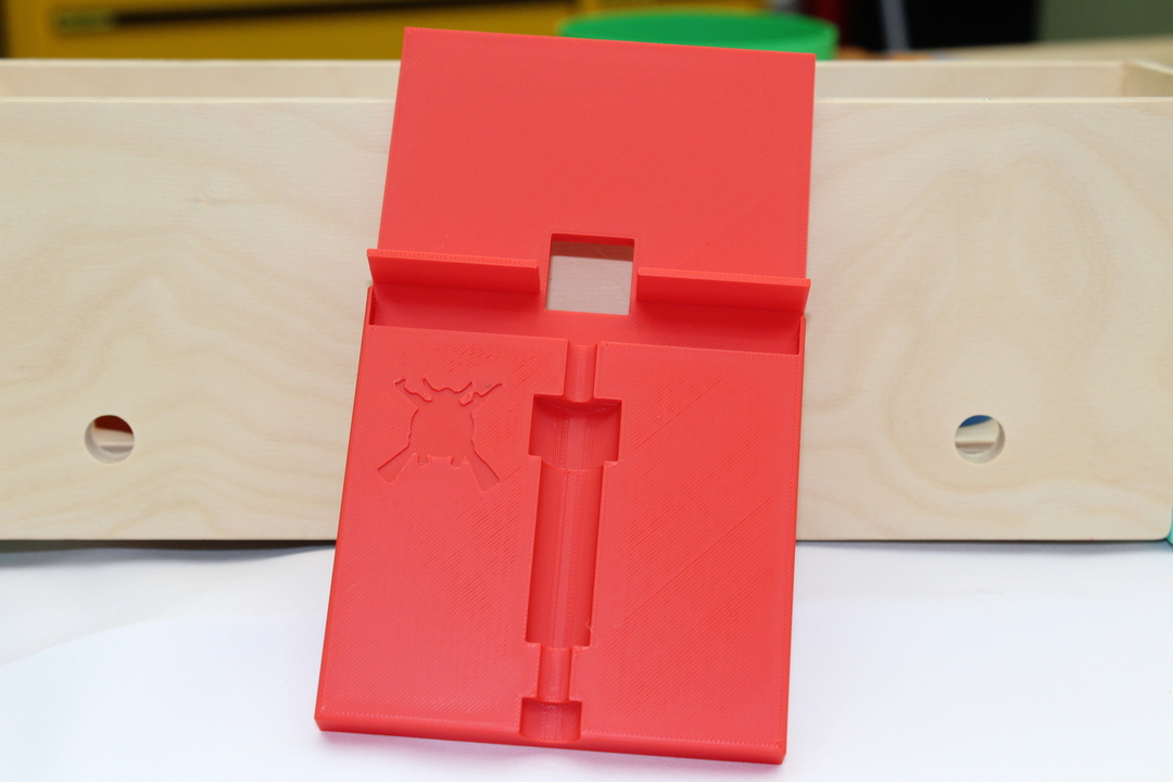
I was watching this video from School of the American Rifle: 5 Colt BCG Physicals (Video link starts at 16:06) and noticed that he had to modify one of the included extension shafts of the iGaging Digital Depth Indicator Set so the firing pin would not go into the threaded hole. That got me thinking about printing something up. This is what I came up with.
iGauging Firing Pin Plug 01
The threaded plugs on the bottom don’t have the ejector notch the the top two have. I like the notched one better. I don’t have to remove the ejector to use. Both are sized to fit snug in the bolt face without getting stuck by the extractor. The plugs also help hold the bolt in place while testing.
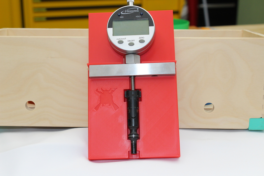
iGauging Firing Pin Plug 02
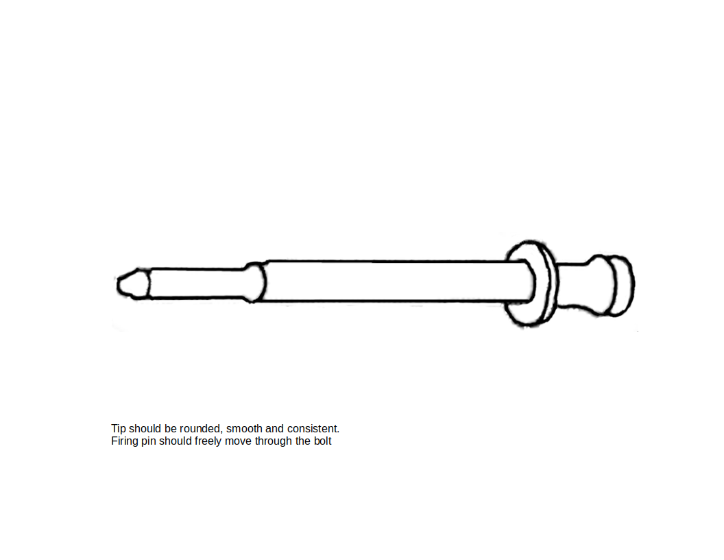
The bottom is very smooth and will be able to help you get accurate and constant readings. AR-15 firing pin protrusion should be 0.028 to 0.036 Check out the reference page for more info.
It is difficult for me to hold everything in place to get an accurate reading. I think I will start working on a holder. More to follow.
All Documents posted on this site are for informational use only. If you make ANY modifications to your Weapons based on this site, you do at your own risk! If done incorrectly, you can render you weapon unsafe and / or unusable.
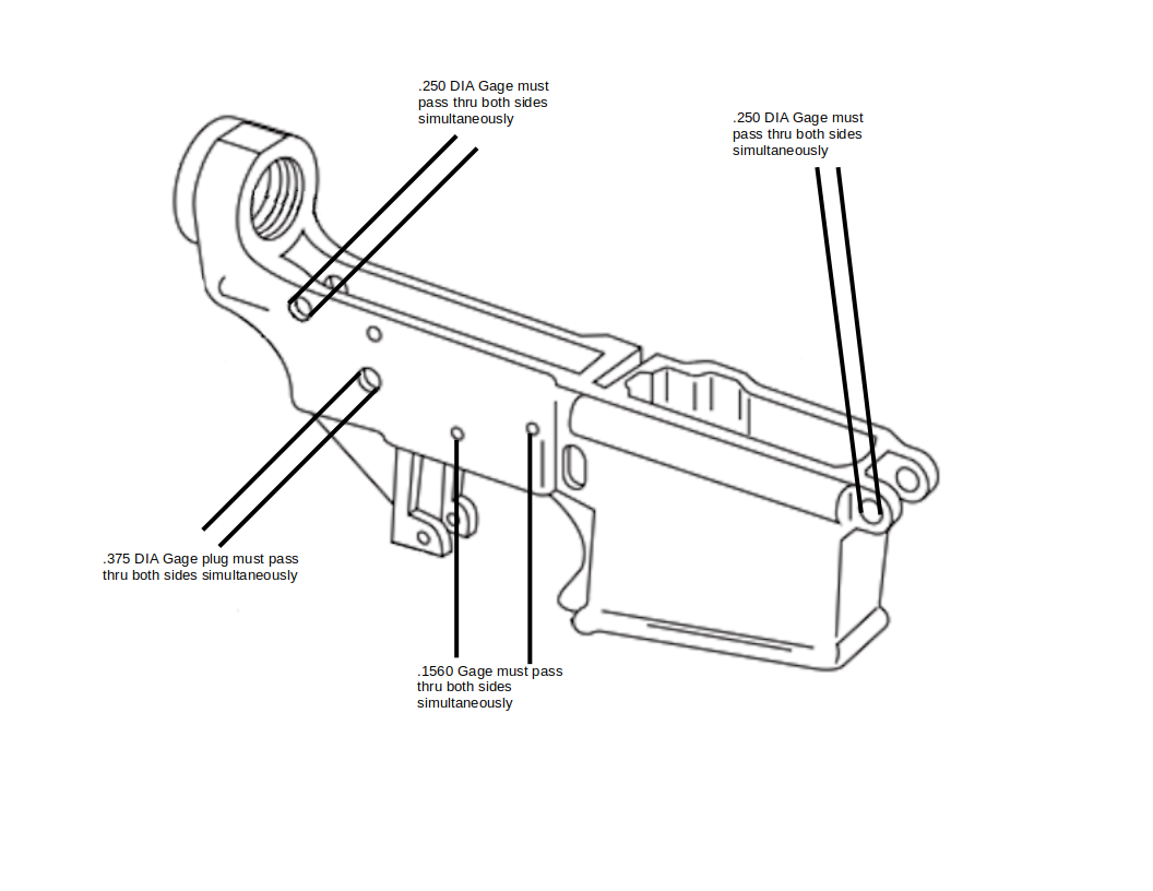
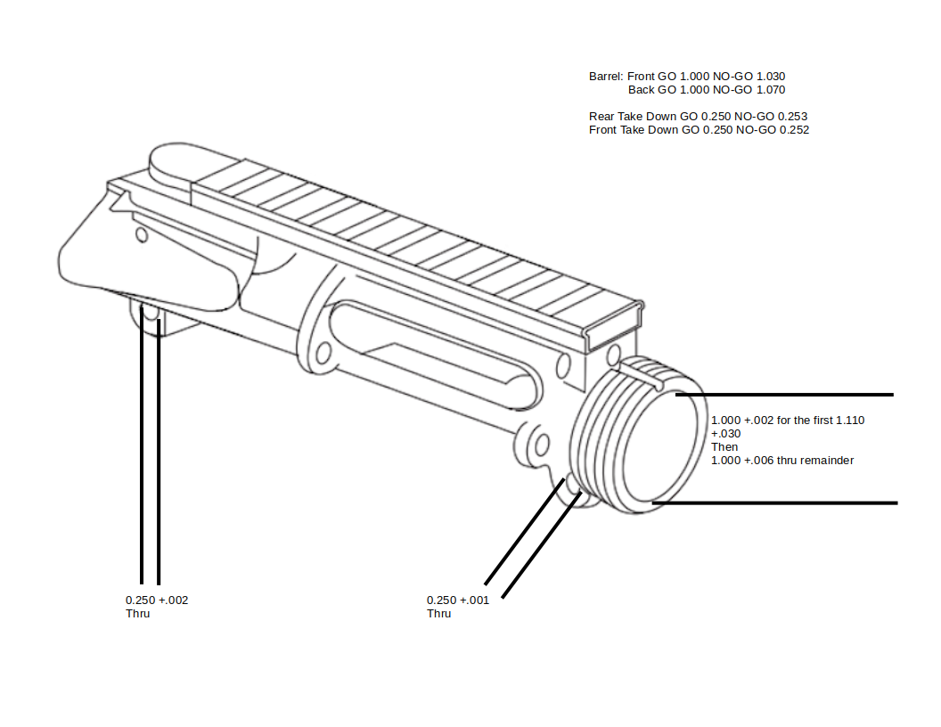
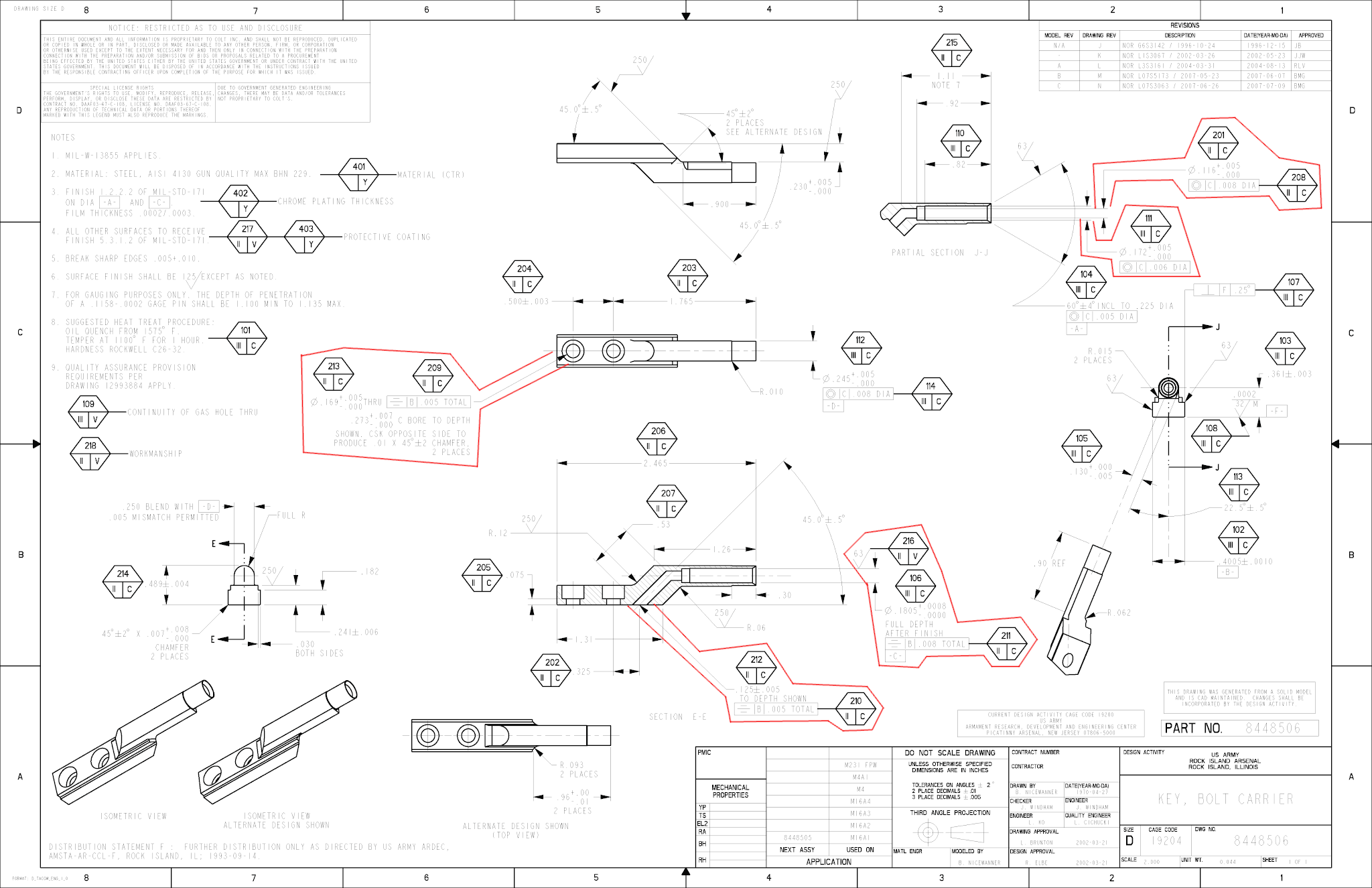
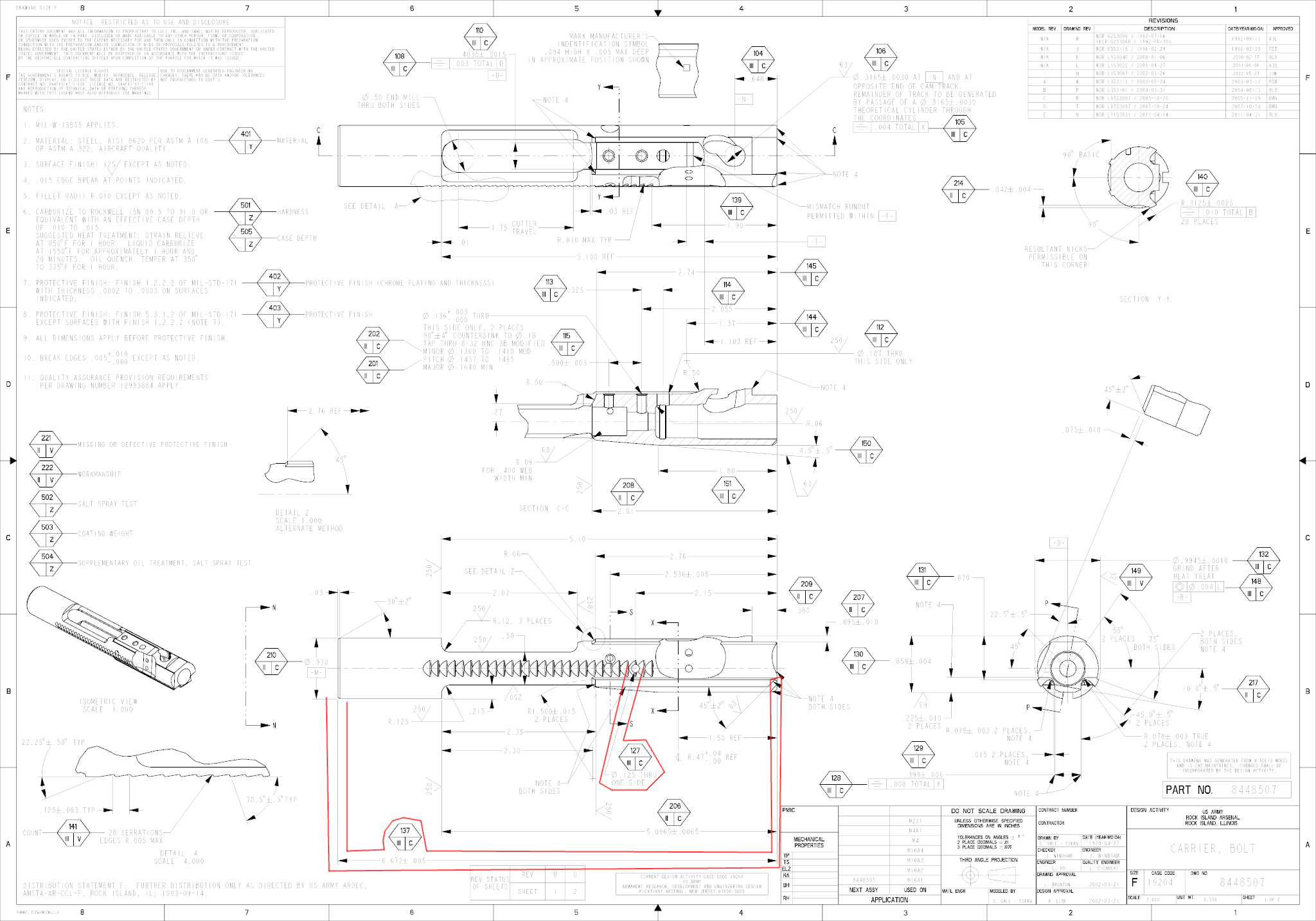
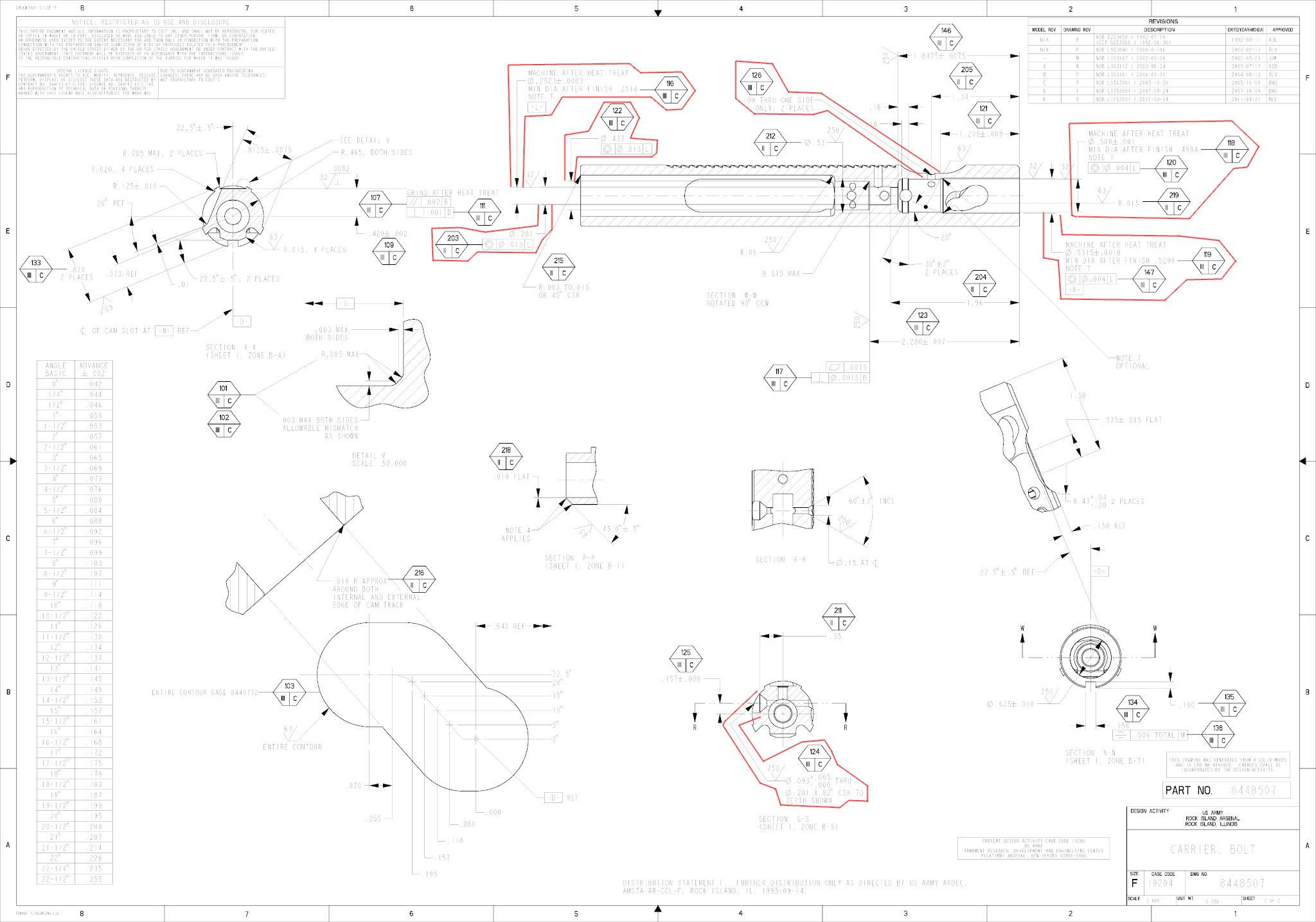
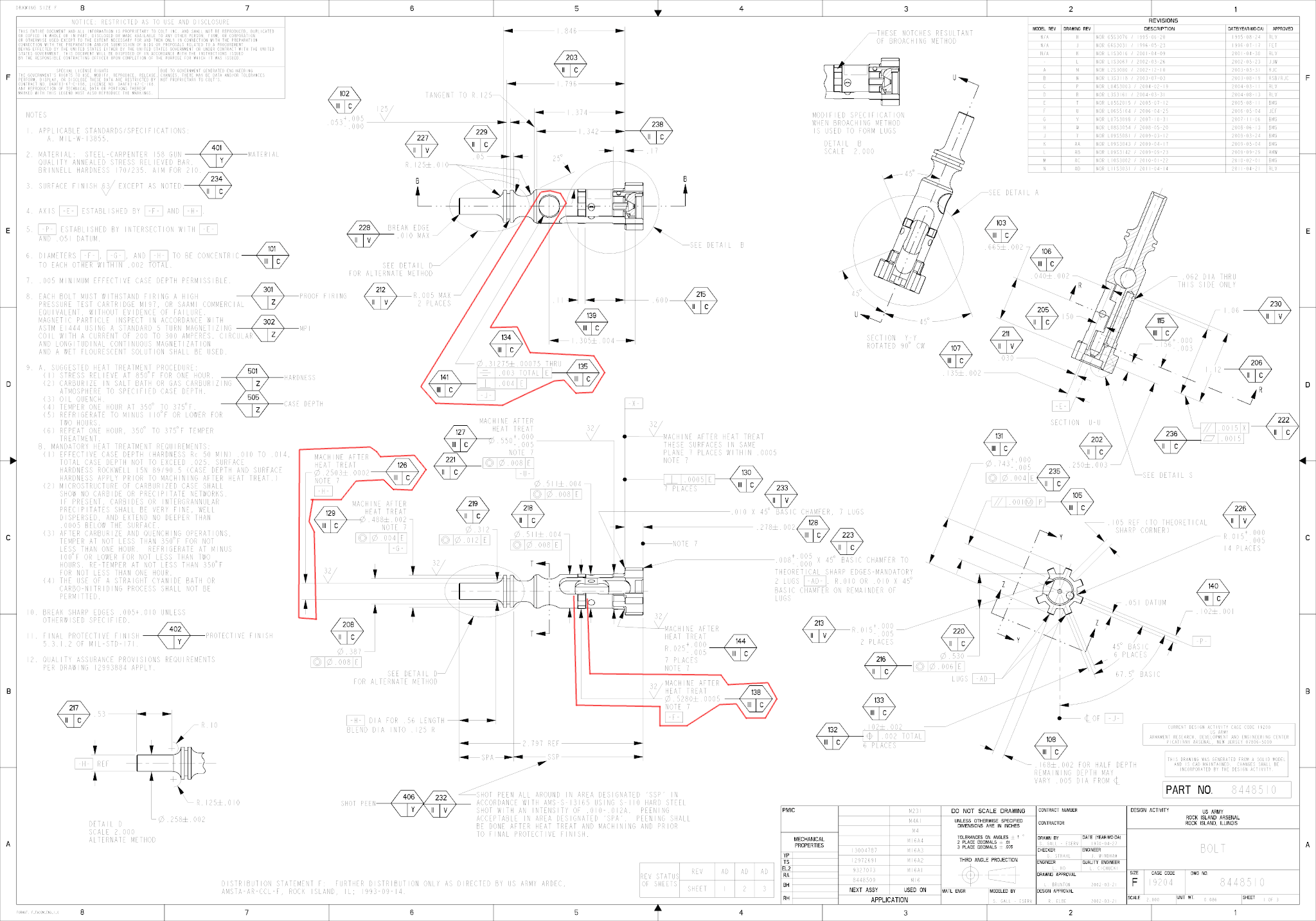
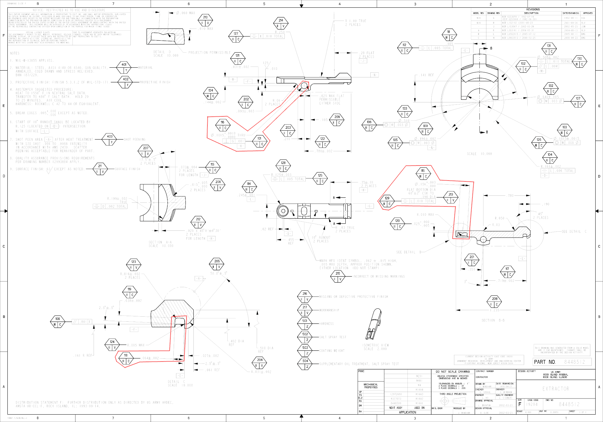
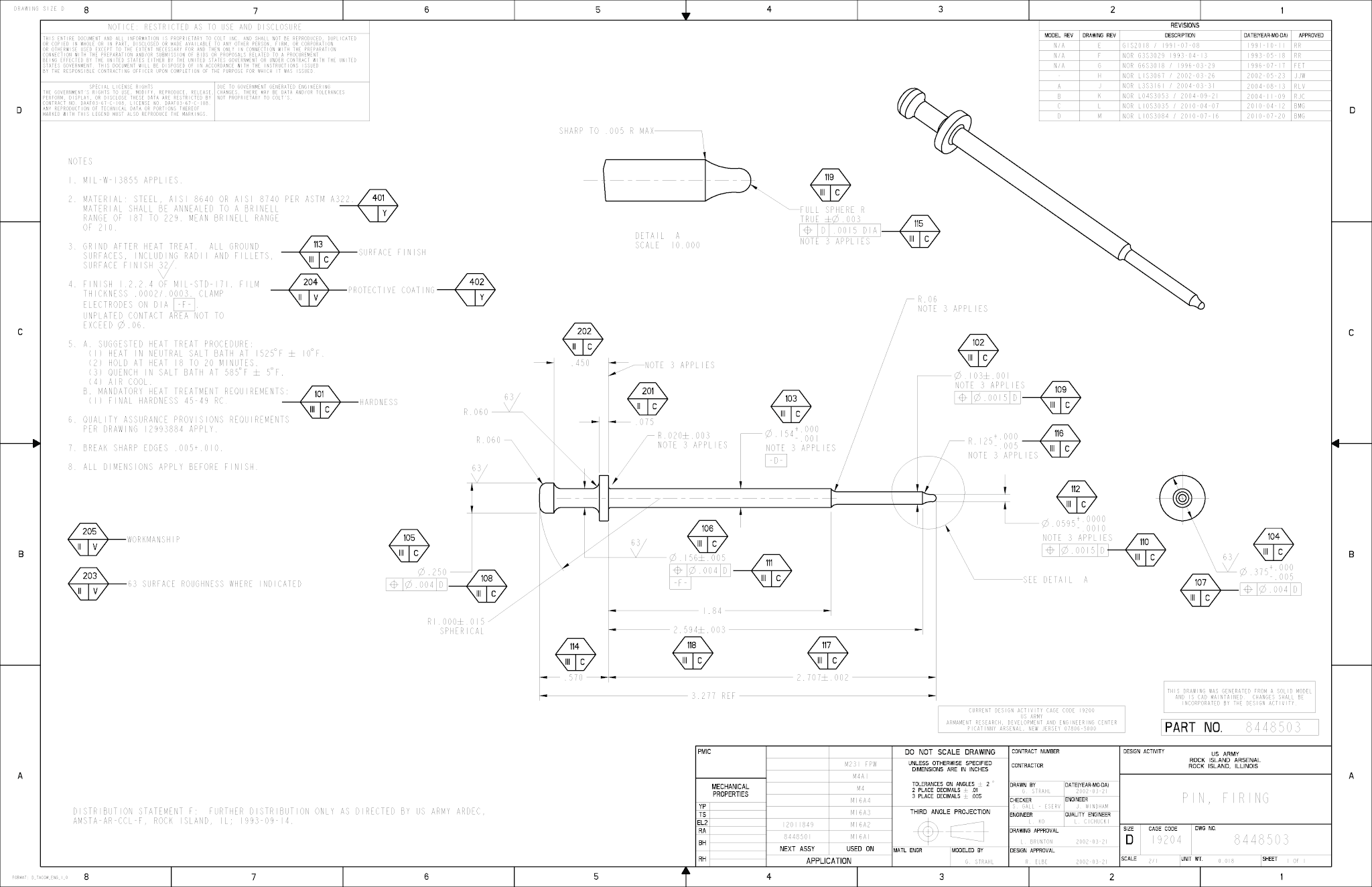
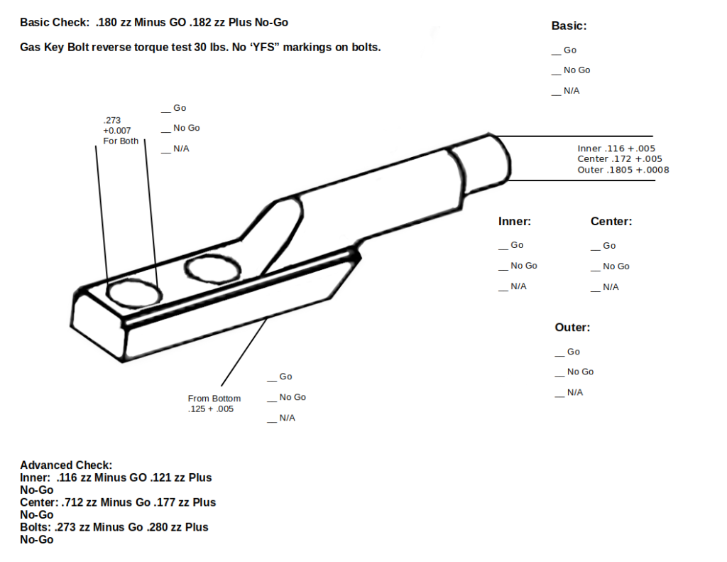
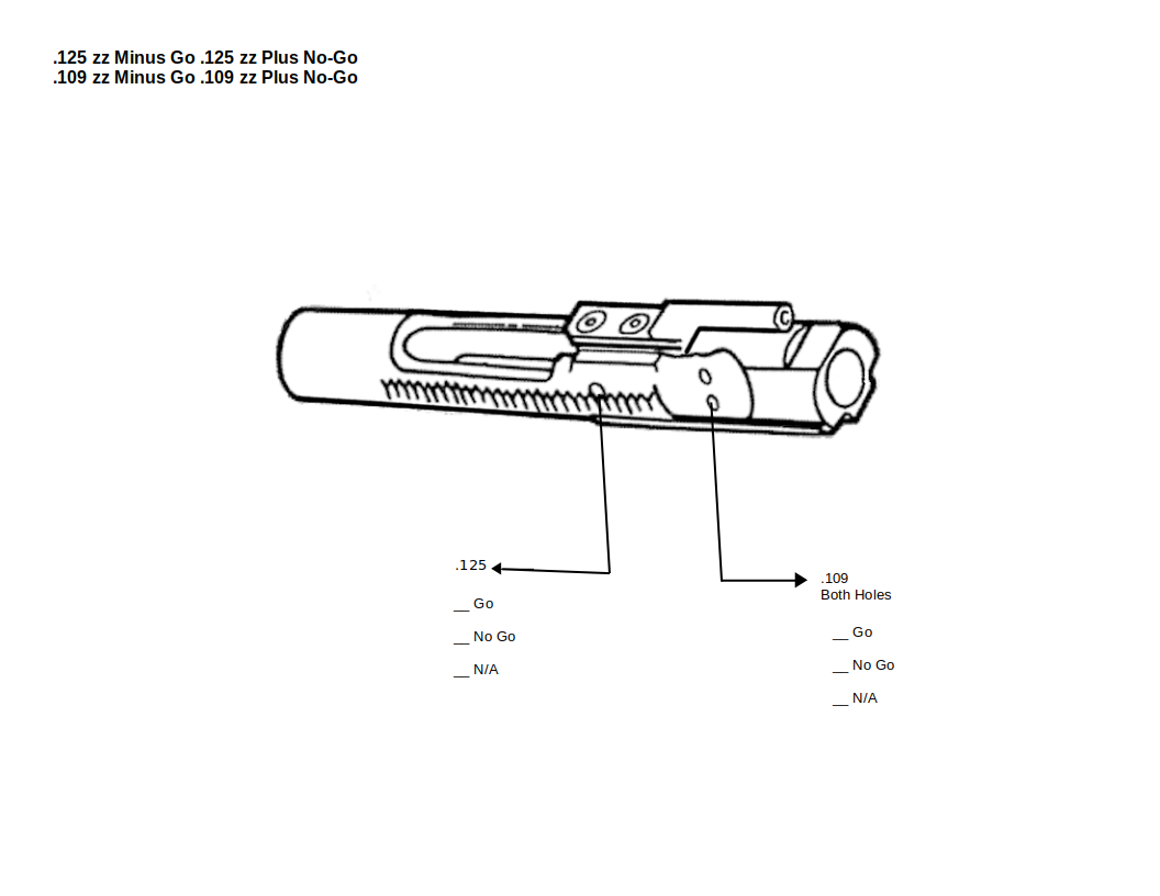
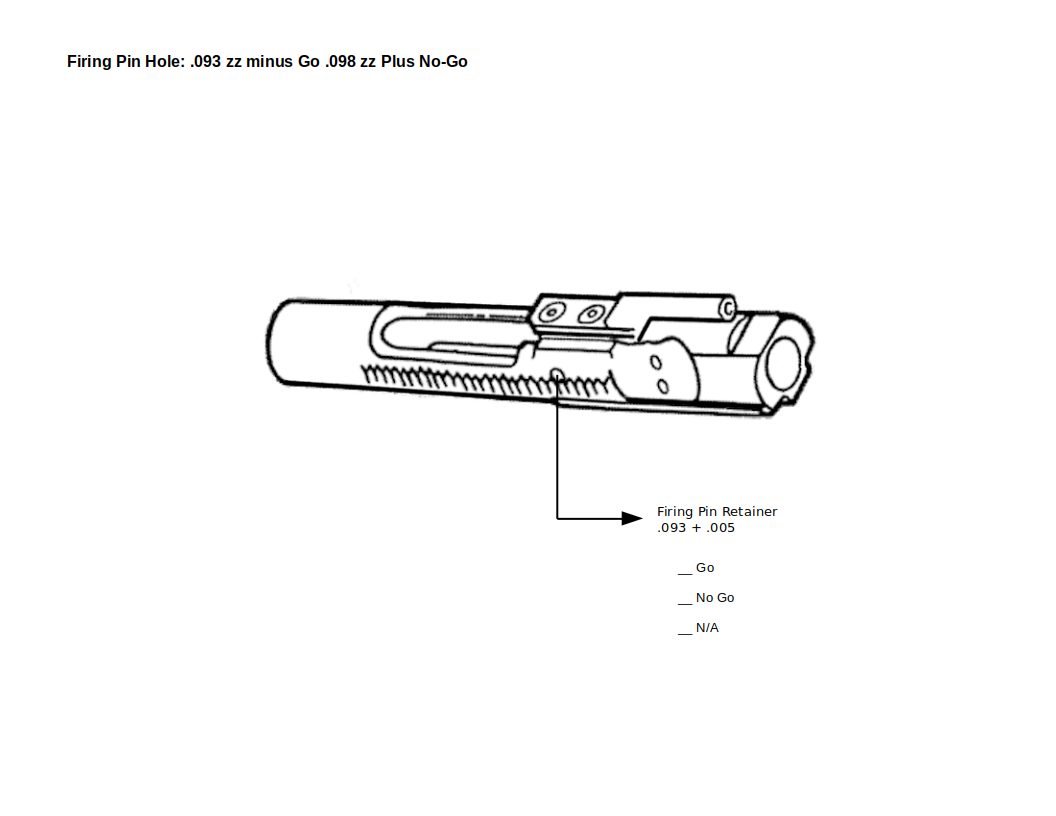
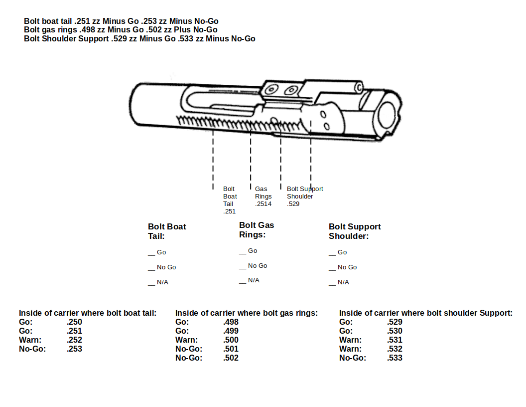
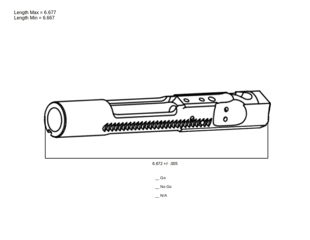
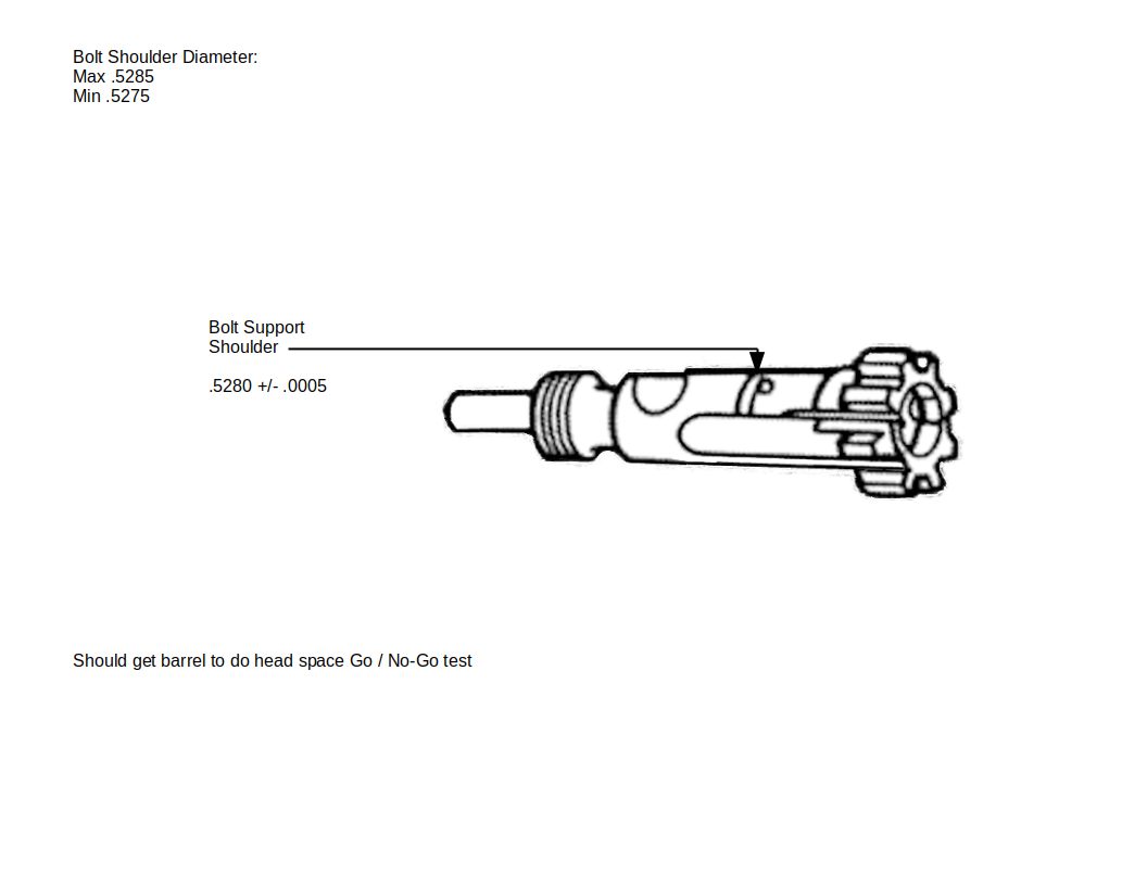
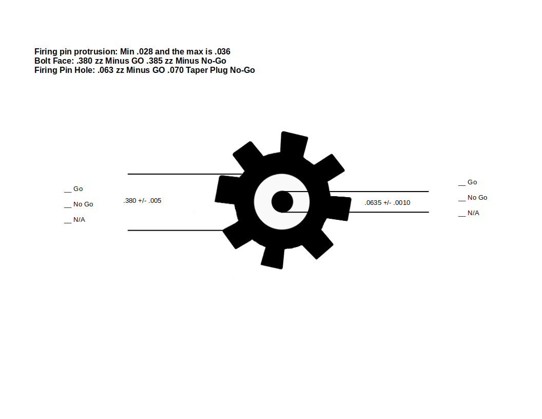
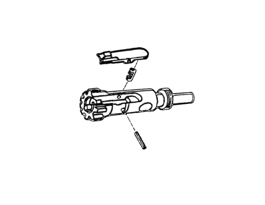
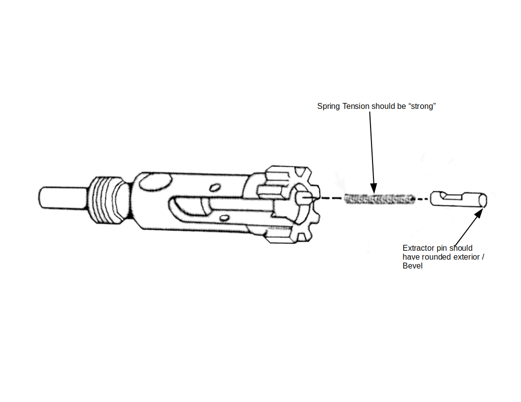
BOLT CARRIER ASSEMBLY0001AR-15 Gas Key Diagram showing markups and dimensions for bolts and all gas sizesAR-15 Bolt Carrier Group Diagram showing markups and dimensions for complete bolt lengthAR-15 Bolt Carrier Group Diagram showing markups and dimensions for 2 internal bolt holes, vent hole,13004787 BOLT ASSEMBLY0001AR-15 Bolt Diagram showing markups and dimensions for Cam Hole, Boat tail Interior, and Bolt RingAR-15 Bolt Diagram showing Boat Tail, Bolt Face and Firing Pin Hole Dimensions and markups8448510 BOLT0003AR-15 Bolt Cam Pin Diagram showing markups and dimensions for diameter and holeAR-15 Extractor Diagram with Markups8448503 PIN, FIRING0001-2048
All Documents posted on this site are for informational use only. If you make ANY modifications to your Weapons based on this site, you do at your own risk! If done incorrectly, you can render you weapon unsafe and / or unusable.
All Documents posted on this site are for informational use only. If you make ANY modifications to your Weapons based on this site, you do at your own risk! If done incorrectly, you can render you weapon unsafe and / or unusable.
All Documents posted on this site are for informational use only. If you make ANY modifications to your Weapons based on this site, you do at your own risk! If done incorrectly, you can render you weapon unsafe and / or unusable.