All Documents posted on this site are for informational use only. If you make ANY modifications to your Weapons based on this site, you do at your own risk! If done incorrectly, you can render you weapon unsafe and / or unusable.
A simple and effective holder to check the spacing from the AR15 gas key and the receiver extension. Use of theBCG to Buffer Space Gauge aka 2 Quarter Tool is documented on many popular blogs and YouTube channels.
I can not find an exact minimum spacing in the Army TM 9-1005-249-23&P Nov 2008. If someone finds it let me know and I will put it in the references.
I like to make things so I came up with this little gem.
It measures 2 quarters / 3.5mm thick and has a few stops to help hold it in place while you are cramming your Bolt Carrier Group back trying to get the gauge.
BCG to Buffer Space Gauge aka 2 Quarter Tool with quarters-0.00
Stops to help hold it:
BCG to Buffer Space Gauge aka 2 Quarter Tool with support stops
Opening to let the BCG slide in:
BCG to Buffer Space Gauge aka 2 Quarter Tool with opening
Showing the gap:
BCG to Buffer Space Gauge aka 2 Quarter Tool in use
All Documents posted on this site are for informational use only. If you make ANY modifications to your Weapons based on this site, you do at your own risk! If done incorrectly, you can render you weapon unsafe and / or unusable.
All Documents posted on this site are for informational use only. If you make ANY modifications to your Weapons based on this site, you do at your own risk! If done incorrectly, you can render you weapon unsafe and / or unusable.
I was watching this video from School of the American Rifle: 5 Colt BCG Physicals (Video link starts at 16:06) and noticed that he had to modify one of the included extension shafts of the iGaging Digital Depth Indicator Set so the firing pin would not go into the threaded hole. That got me thinking about printing something up. This is what I came up with.
iGauging Firing Pin Plug 01
The threaded plugs on the bottom don’t have the ejector notch the the top two have. I like the notched one better. I don’t have to remove the ejector to use. Both are sized to fit snug in the bolt face without getting stuck by the extractor. The plugs also help hold the bolt in place while testing.
iGauging Firing Pin Plug 02
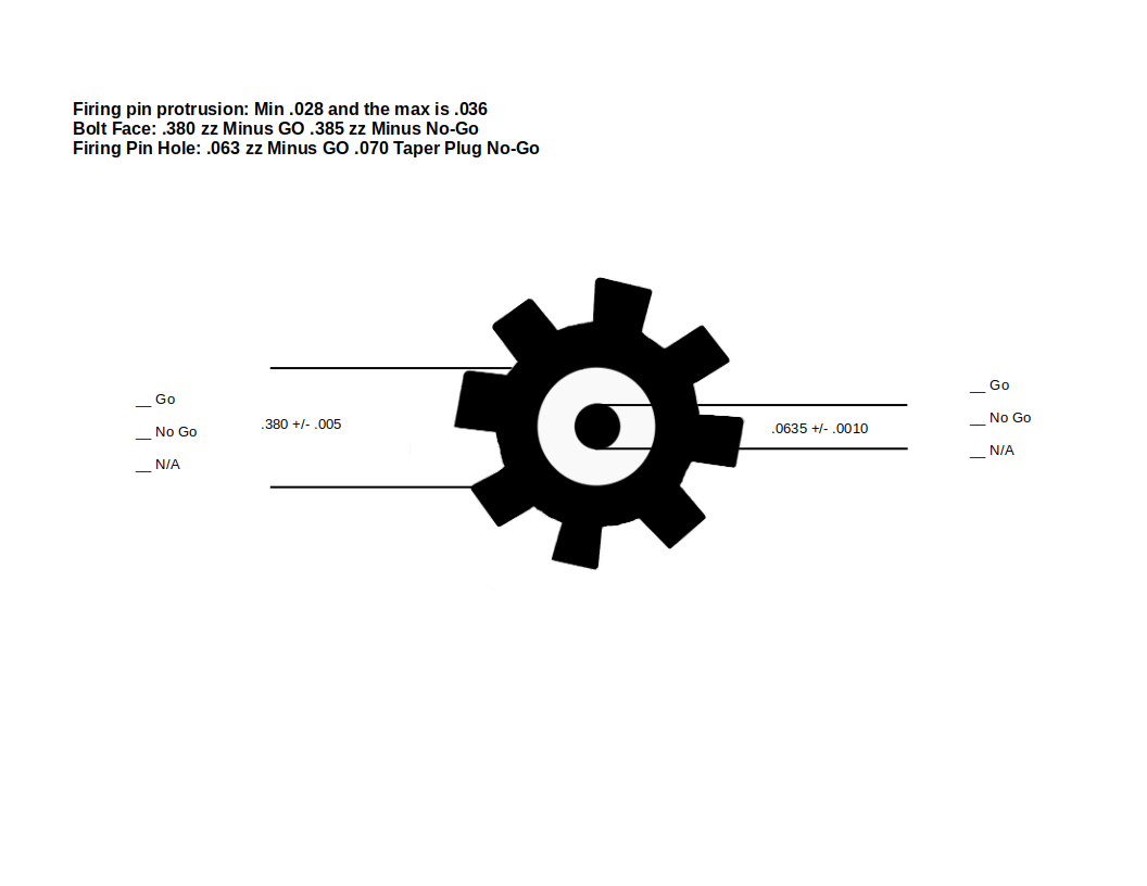
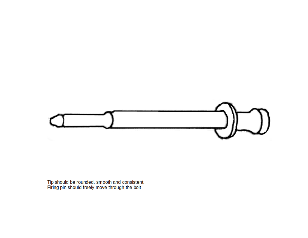
The bottom is very smooth and will be able to help you get accurate and constant readings. AR-15 firing pin protrusion should be 0.028 to 0.036 Check out the reference page for more info.
It is difficult for me to hold everything in place to get an accurate reading. I think I will start working on a holder. More to follow.
All Documents posted on this site are for informational use only. If you make ANY modifications to your Weapons based on this site, you do at your own risk! If done incorrectly, you can render you weapon unsafe and / or unusable.
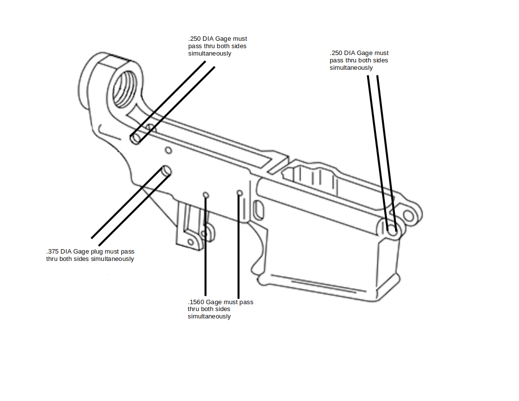
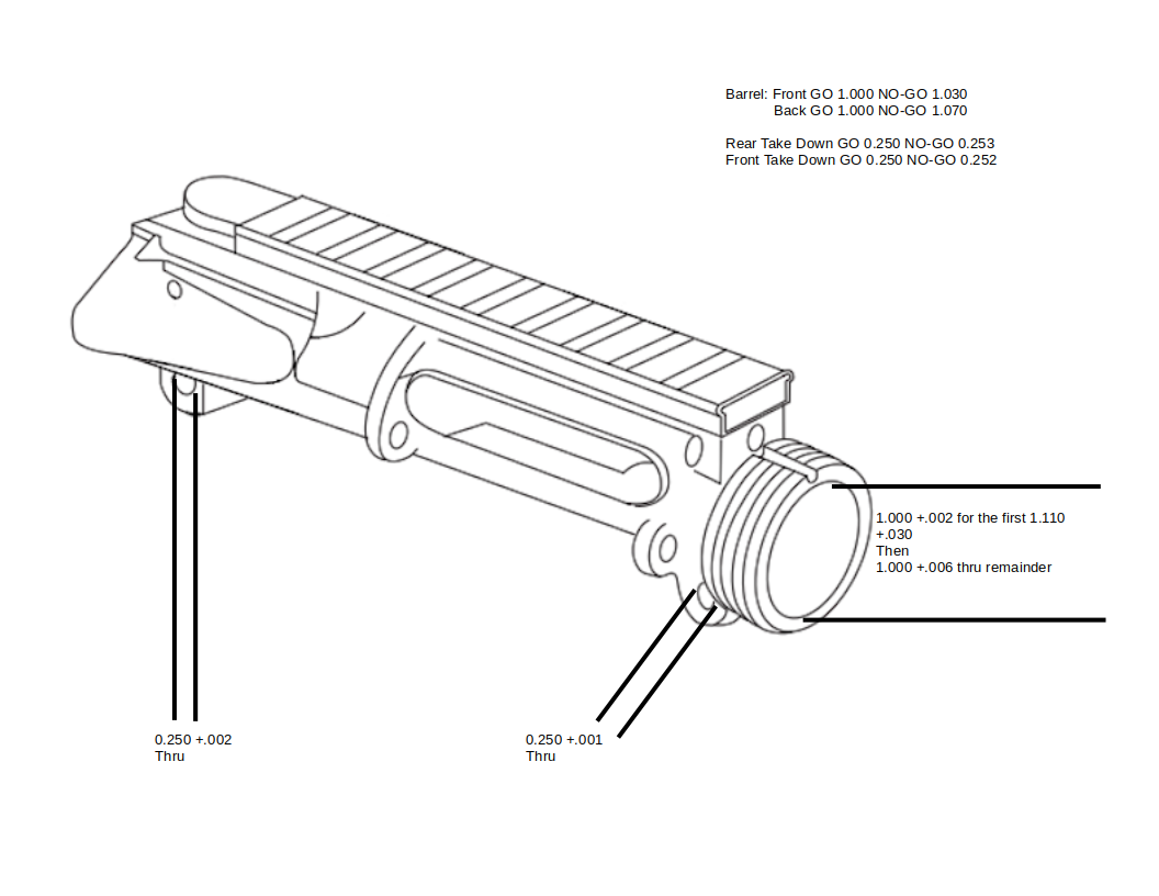
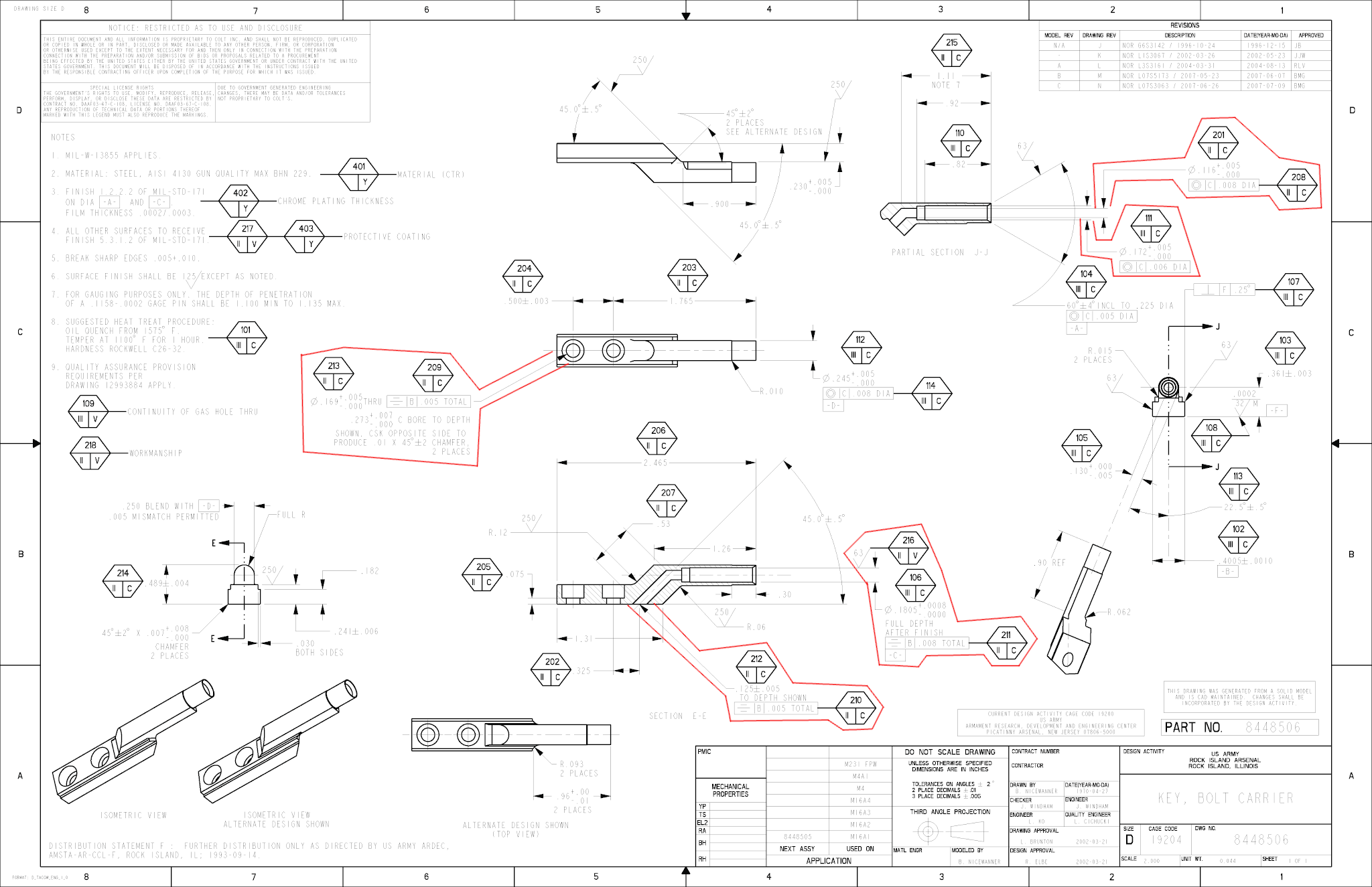
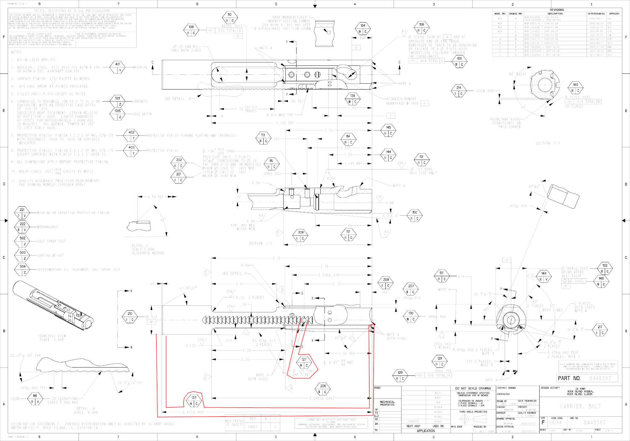
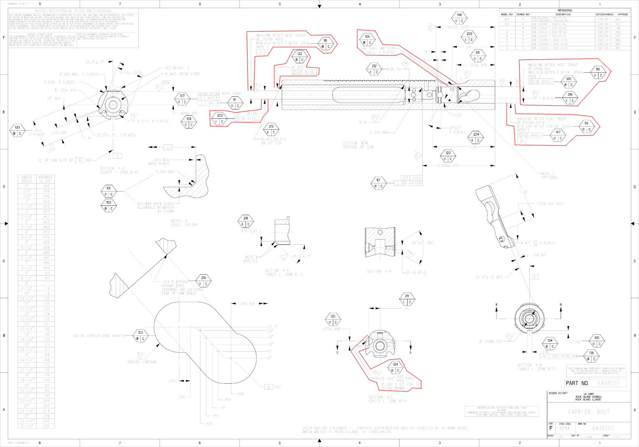
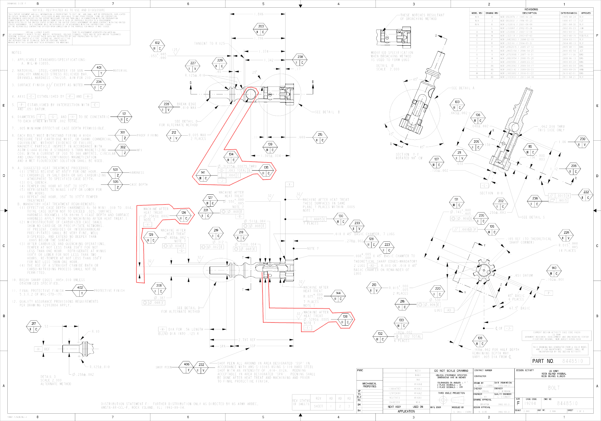
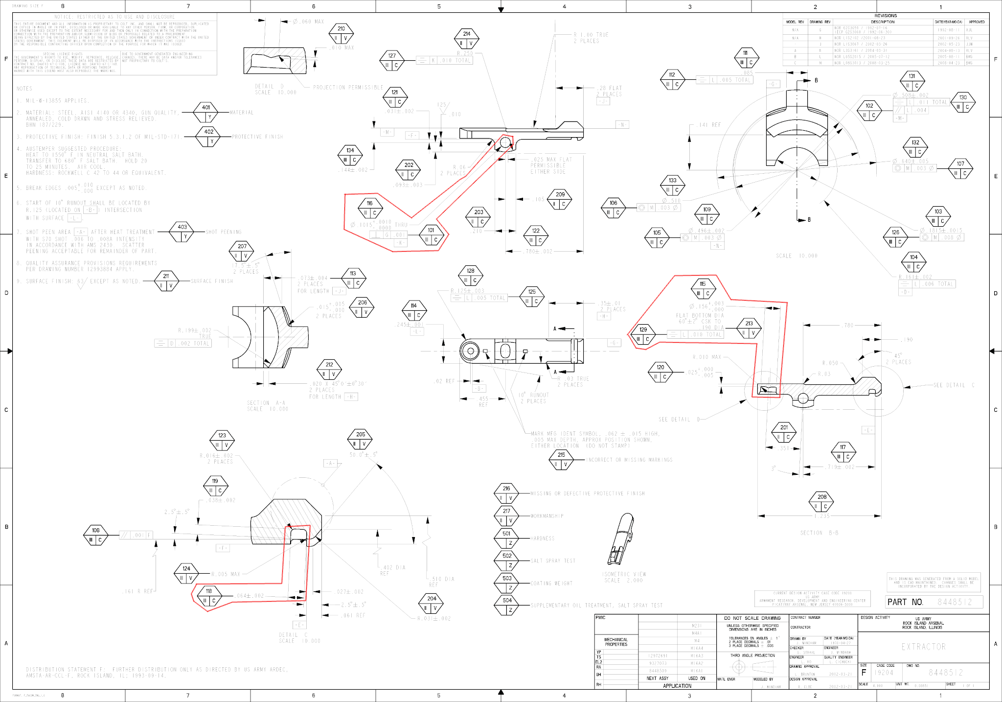
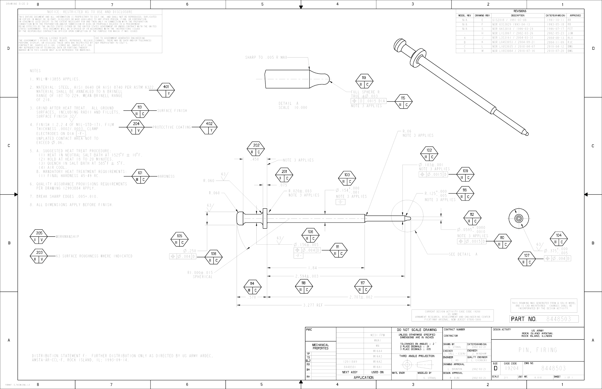
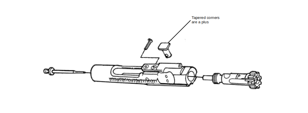
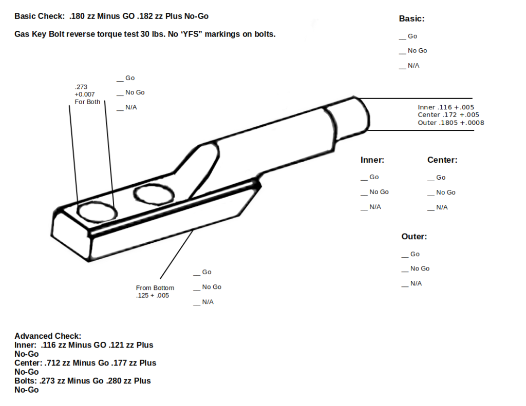
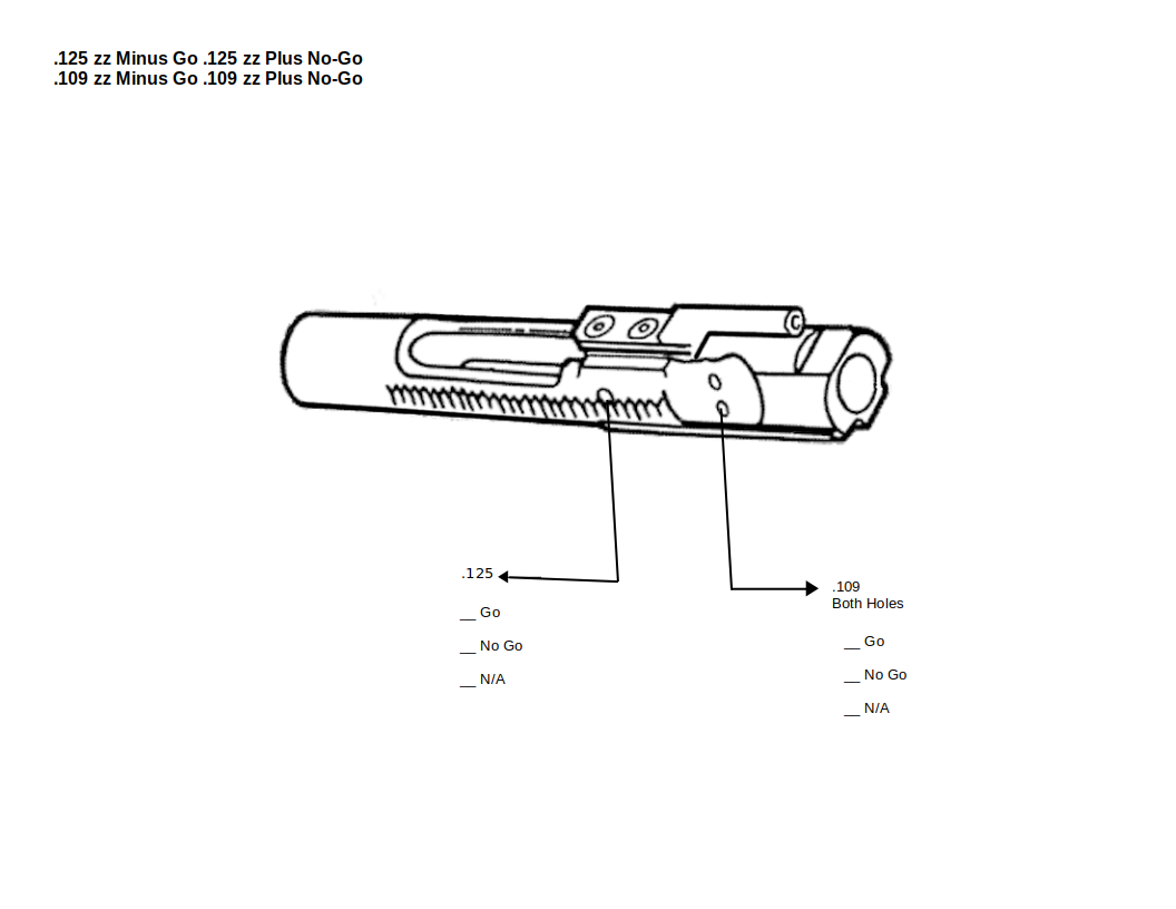
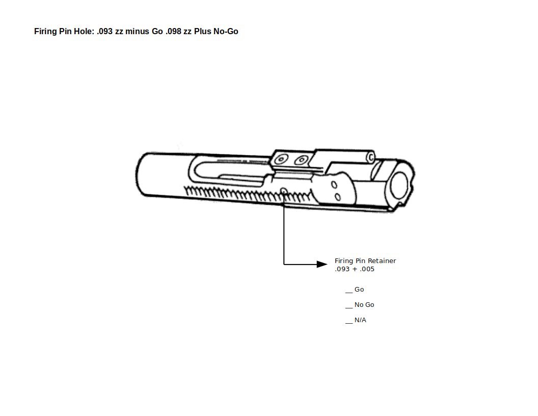
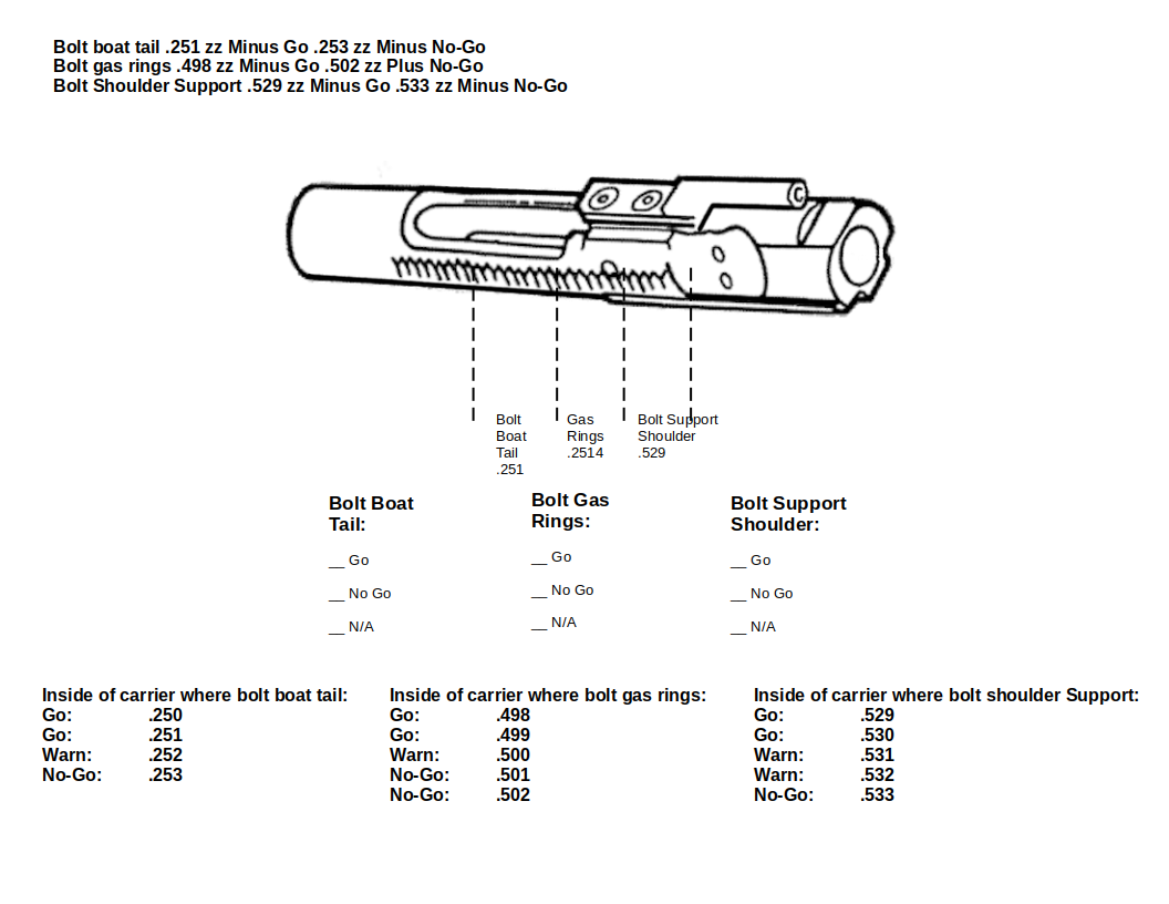
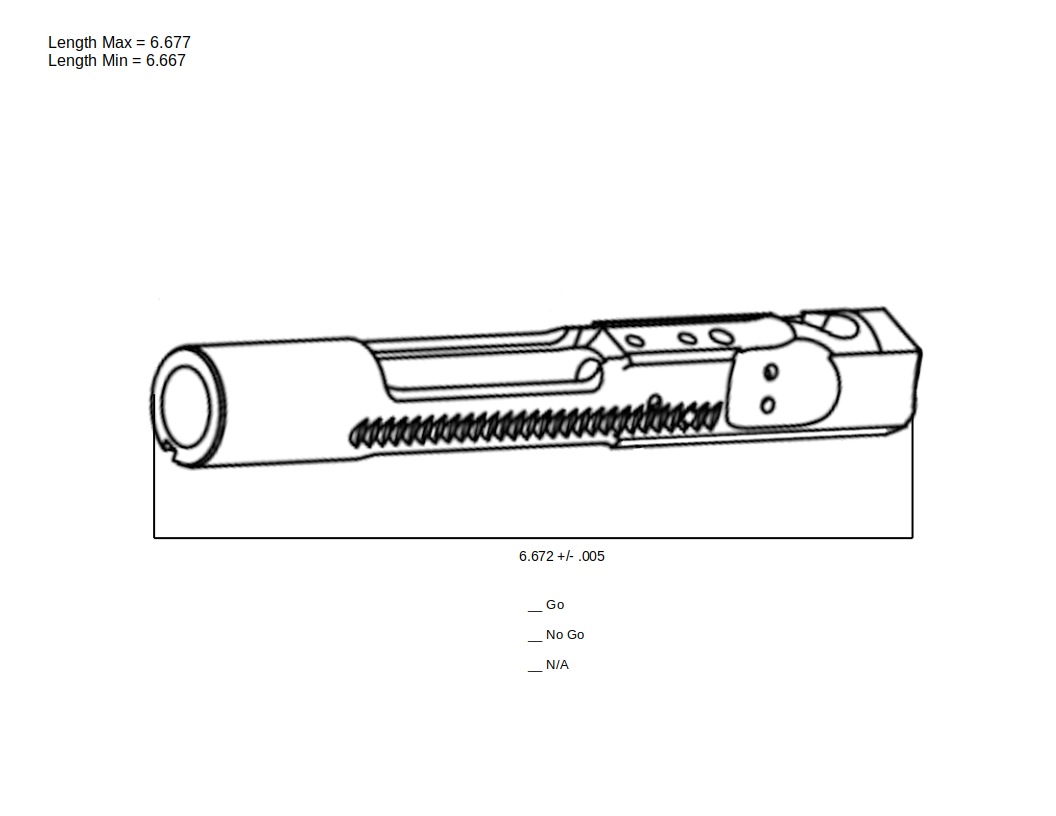
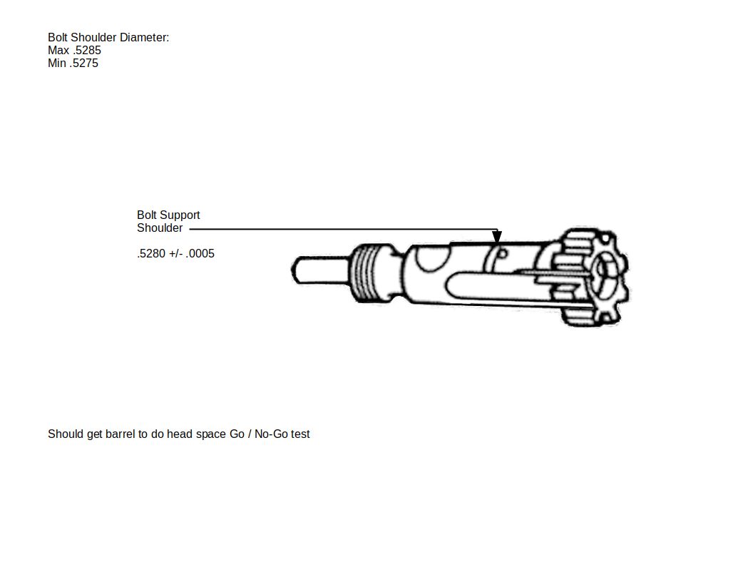
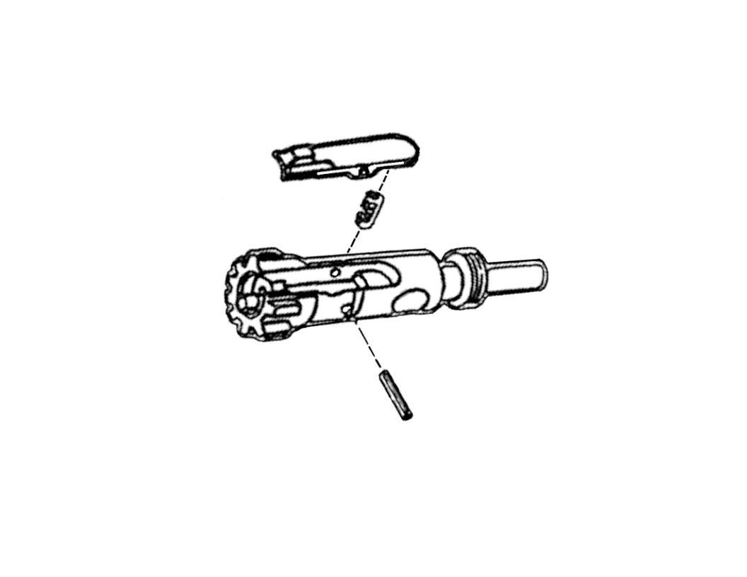
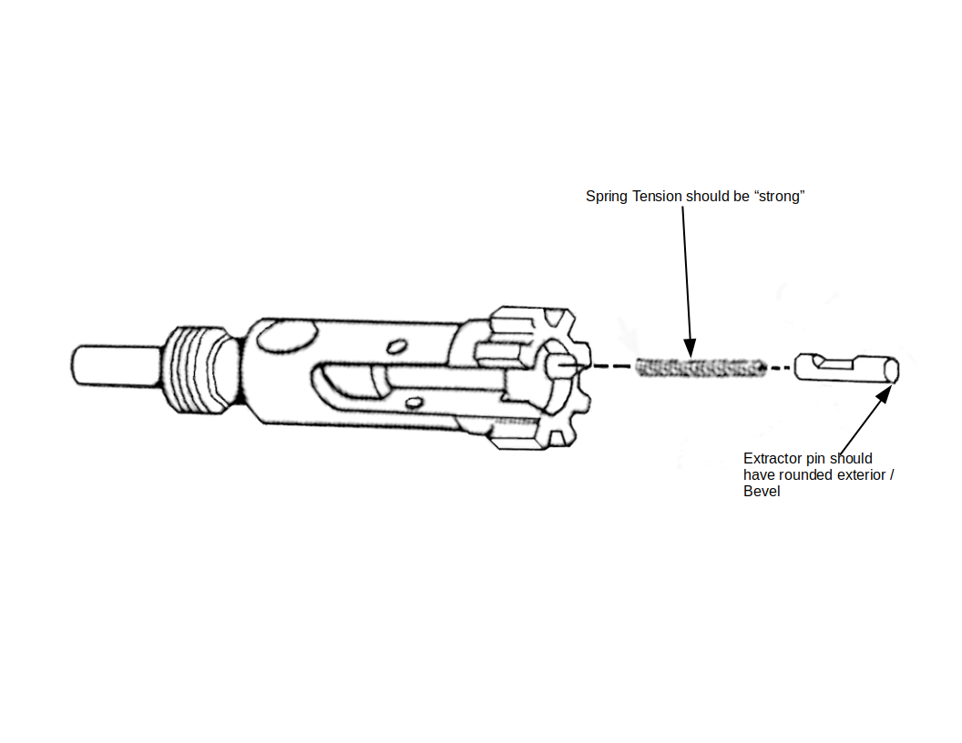
BOLT CARRIER ASSEMBLY0001AR-15 Gas Key Diagram showing markups and dimensions for bolts and all gas sizesAR-15 Bolt Carrier Group Diagram showing markups and dimensions for complete bolt lengthAR-15 Bolt Carrier Group Diagram showing markups and dimensions for 2 internal bolt holes, vent hole,13004787 BOLT ASSEMBLY0001AR-15 Bolt Diagram showing markups and dimensions for Cam Hole, Boat tail Interior, and Bolt RingAR-15 Bolt Diagram showing Boat Tail, Bolt Face and Firing Pin Hole Dimensions and markups8448510 BOLT0003AR-15 Bolt Cam Pin Diagram showing markups and dimensions for diameter and holeAR-15 Extractor Diagram with Markups8448503 PIN, FIRING0001-2048
All Documents posted on this site are for informational use only. If you make ANY modifications to your Weapons based on this site, you do at your own risk! If done incorrectly, you can render you weapon unsafe and / or unusable.
All Documents posted on this site are for informational use only. If you make ANY modifications to your Weapons based on this site, you do at your own risk! If done incorrectly, you can render you weapon unsafe and / or unusable.
All Documents posted on this site are for informational use only. If you make ANY modifications to your Weapons based on this site, you do at your own risk! If done incorrectly, you can render you weapon unsafe and / or unusable.