We have added a new Glock pin set, that you can buy HERE, to our collection. We listened to our customers who said that they wanted a longer handle for a better grip. The length of the pins is the same on both versions.
Here you go:
Glock Pin with longer handle and holder 2Glock Pin Long Handle in Holder
There a 3 pins in 2 different sizes, 1 large and 2 small.
Glock Pin v2 Sizes
Shown in the below image Gen 4 and prior used 3 pins:
Glock Pins Gen 4 marked pins
While the Gen 5 and later only use 2:
Glock Pins Gen 6 marked pins
We want you to be able to use our tools on all you can, so we include 3.
Here is a picture with the pins used on a Glock 17 Gen 4:
Glock Pin Set in G17 Gen 4 Top
I will be making a usage video and posting it here very soon.
Hit us up with comments or requestsAll Documents posted on this site are for informational use only. If you make ANY modifications to your Weapons based on this site, you do at your own risk! If done incorrectly, you can render you weapon unsafe and / or unusable.
All Documents posted on this site are for informational use only. If you make ANY modifications to your Weapons based on this site, you do at your own risk! If done incorrectly, you can render you weapon unsafe and / or unusable.
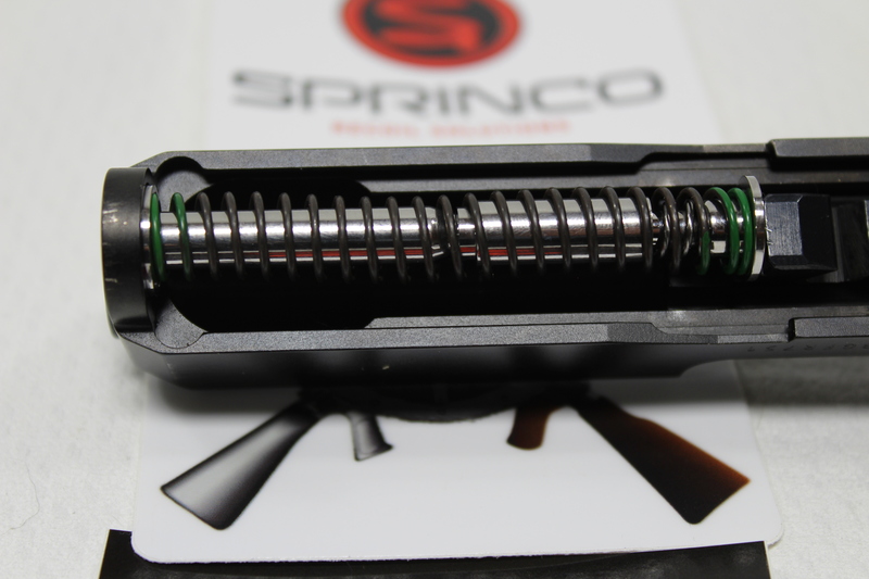
I just picked up the Recoil Management System, Versatility Kit from the great folks at SpringCO for my Glock 19 Gen 5. I wanted to show what I did to get it installed. It was pretty straight forward and easy to do.
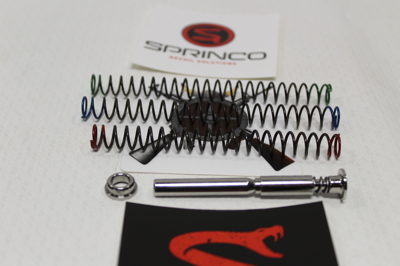
Here are the parts that came in the package.
SpringCO Glock Recoil Management System Whats Included
I am going to install the Green 13# spring. As this is a non-captured setup I will be trying the 15 and 17 pound springs in the near future and keeping the one I like best and works best for my situation.
SpringCO Glock Recoil Management System what I am installing
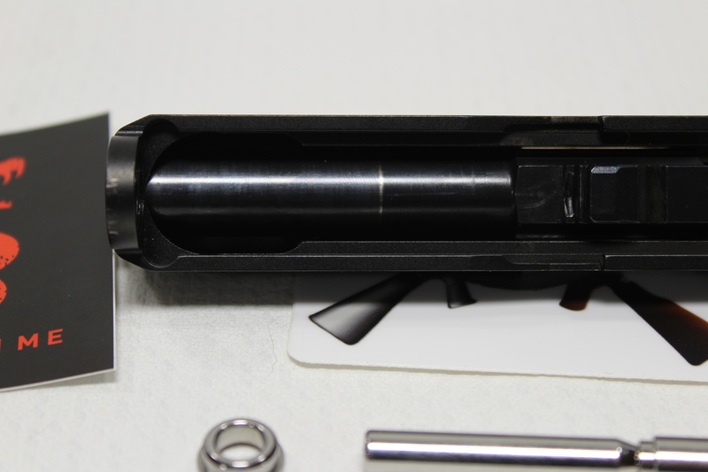
Remove the existing recoil spring
SpringCO Glock Recoil Management System remove the old
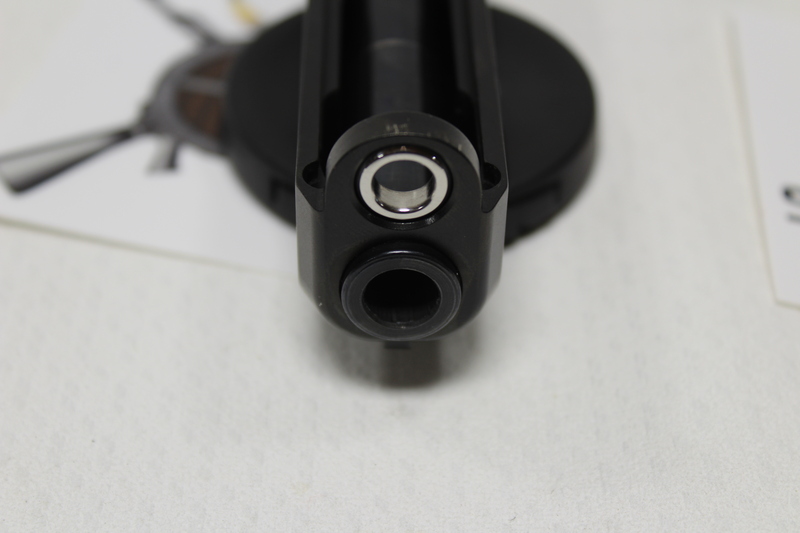
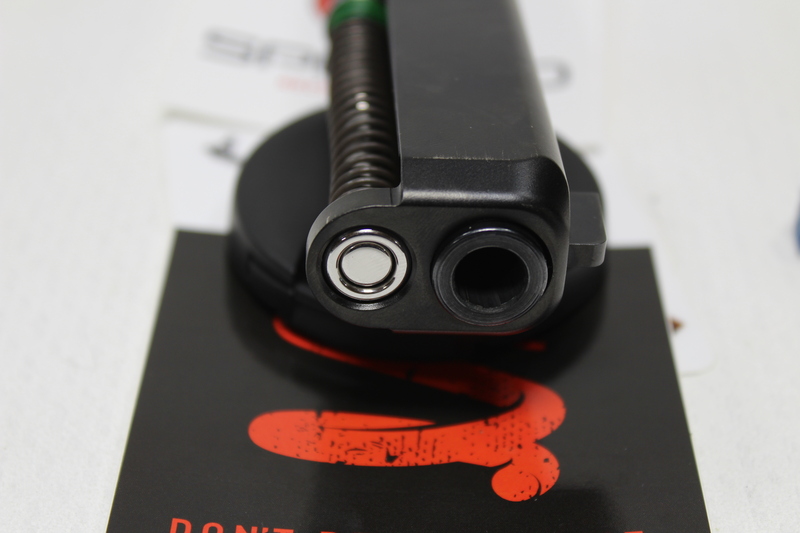
Make sure the Guide Rod Forward Bushing goes in with the small section forward as show in the picture:
SpringCO Glock Recoil Management System Bushing direction
Here are a couple more shots of what it should look like:
SpringCO Glock Recoil Management System Bushing Direction 2
Front:
SpringCO Glock Recoil Management System Bushing Direction front view
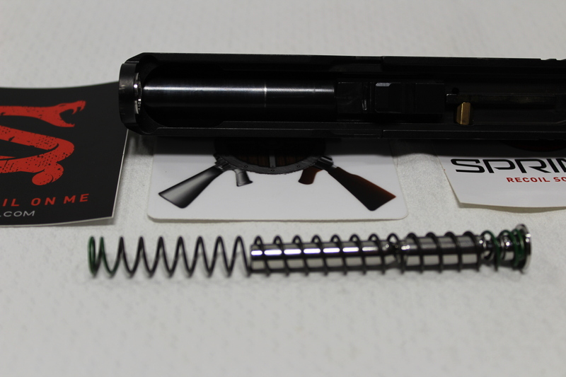
Slide the spring you want to use on the guide rod:
SpringCO Glock Recoil Management System Bushing slide on the spring
Place the spring in the Guide Rod Forward Bushing and carefully push in place. The guide rod will fit into the hole in the bushing.
The guide rod will fit into the hole in the bushing.
After everything is lined up everything will fit like the original.
After everything is lined up everything will fit like the original.
Front shot of how the bushing should look:
SpringCO Glock Recoil Front shot of how the bushing should look
There are several videos that explain what is going on with the system when it is installed. I wanted to share my experience getting it installed.
All Documents posted on this site are for informational use only. If you make ANY modifications to your Weapons based on this site, you do at your own risk! If done incorrectly, you can render you weapon unsafe and / or unusable.
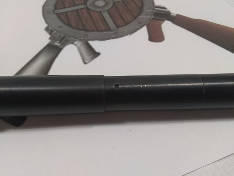
Dimpling your barrel to help secure your gas block is key to ensuring the gas system of your AR will continue to function correctly. A loose gas block can cause havoc to the cycling of your AR. I dimple at least once directly under the gas port. I can dimple twice, but realize that different manufactures have different spacing for the second screw. If you want or need to change your existing gas block you have to use a gas block with the same set screw spacing. Not a huge issue for some, but if the new gas block you want has a different spacing you would need to get another barrel to accommodate the different spacing.
All Documents posted on this site are for informational use only. If you make ANY modifications to your Weapons based on this site, you do at your own risk! If done incorrectly, you can render you weapon unsafe and / or unusable.
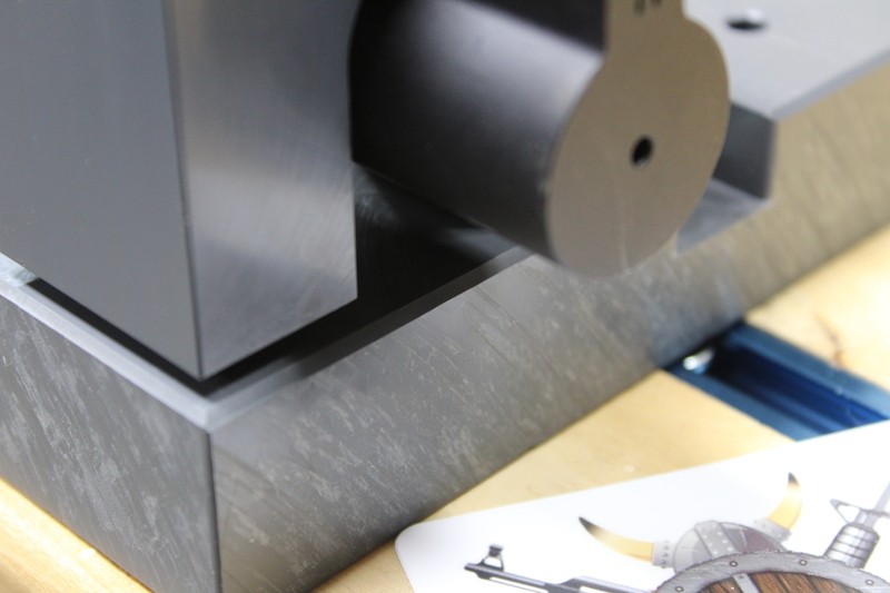
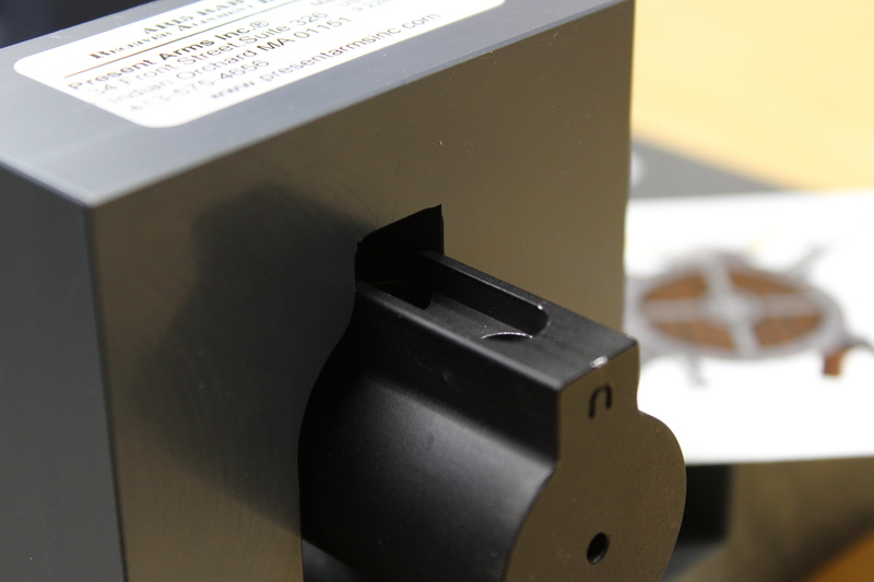
My Present Arms Gunners Mount Kit is awesome. The one thing I wanted different was the Receiver Alignment Block. It does not seem to fit right on non-mil spec buffer tubes I work on. How can they know all the sizes?
You can see the gap here, it will not seat all the way.
You can see the gap here, it will not seat all the way.
And that is because the buffer tube rail is too wide.
And that is because the buffer tube rail is too wide.
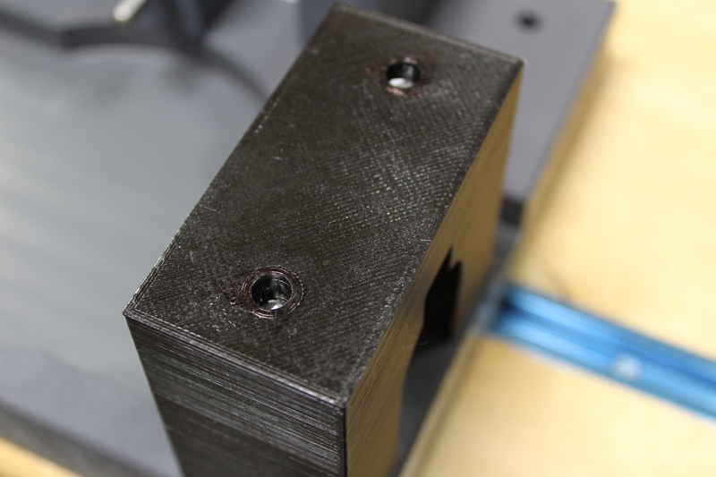
So I do what I do and made one. Seats all the way down
So I do what I do and made one. Seats all the way down
And tightly fits the buffer tube rail
And tightly fits the buffer tube rail
The metal rod it ¼ inch and I cut it down to just below the top.
The metal rod it ¼ inch and I cut it down to just below the top.
Then topped it off with a couple of the included caps.
Then topped it off with a couple of the included caps.
All Documents posted on this site are for informational use only. If you make ANY modifications to your Weapons based on this site, you do at your own risk! If done incorrectly, you can render you weapon unsafe and / or unusable.
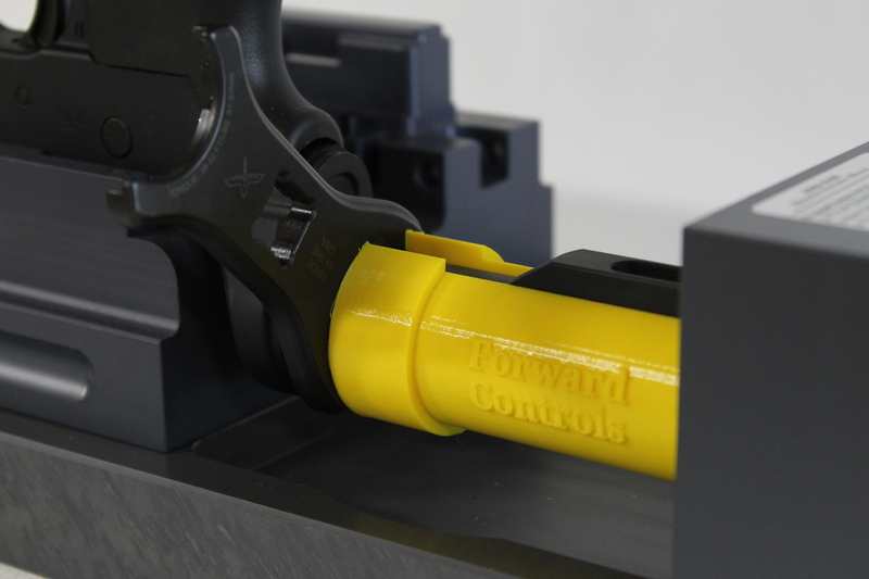
A sleeve to help hold your castle nut wrench firmly in place while cranking it down on your Present Arms Gunners Mount.
I can not claim this idea as my own, I was watching this video from School of the American Rifle and though “What a great idea”. I did not have any 1 ¼ inch PVC laying around, but I do have a 3D printer and PLA. This is what I came up with for the below wrenches.
Forward Controls:
A sleeve to help hold your castle nut wrench firmly in place Forward ControlsA sleeve to help hold your castle nut wrench firmly in place Forward Controls
Magpul:
A sleeve to help hold your castle nut wrench firmly in place MagpulA sleeve to help hold your castle nut wrench firmly in place Magpul
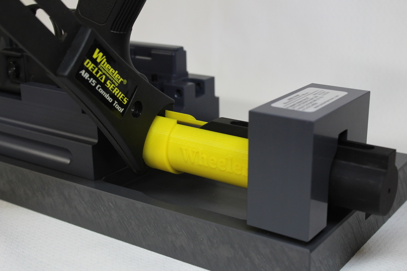
Wheeler
A sleeve to help hold your castle nut wrench firmly in place Wheeler
Family Shot:
A sleeve to help hold your castle nut wrench firmly in place all 3
Present Arms on all sizes:
A sleeve to help hold your castle nut wrench firmly in place Present Arms
All Documents posted on this site are for informational use only. If you make ANY modifications to your Weapons based on this site, you do at your own risk! If done incorrectly, you can render you weapon unsafe and / or unusable.
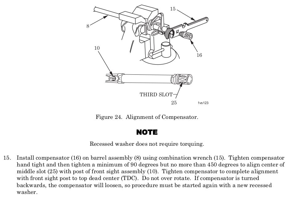
AR Compensator (Flash hider) No Torque, timing value with the procedure in the Army TM. Hand tight and then tighten a minimum of 90 degrees but no more than 450 degrees to timing. Don’t over tighten, don’t loosen.
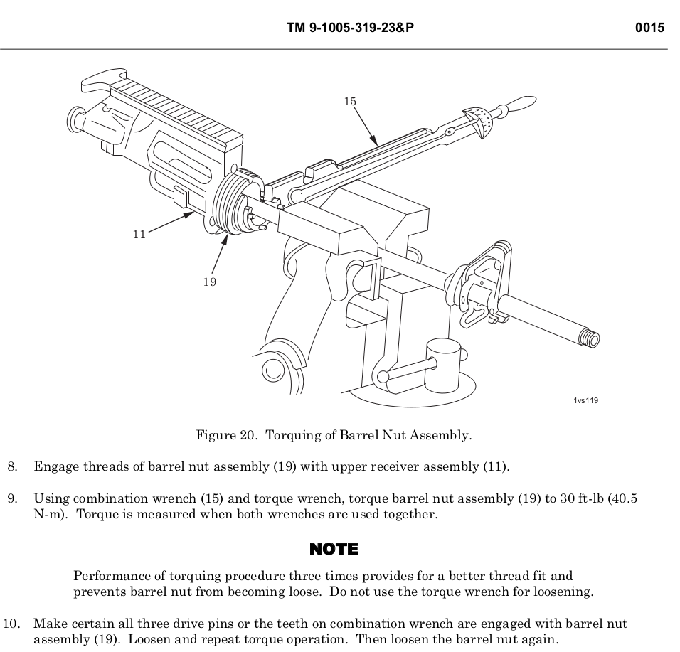
AR Barrel Nut 30 Ft. lbs. Minimum, not to exceed 80 Ft. Lbs. to align the next slot in the barrel nut. The 80 Ft. Lbs is not stated in the TM, but I don’t know how you would line up the gas tube, without going over 30 Ft. Lbs. Unless you use shims. I don’t think most folks will have any laying around. This torque spec is common across the community and internet.
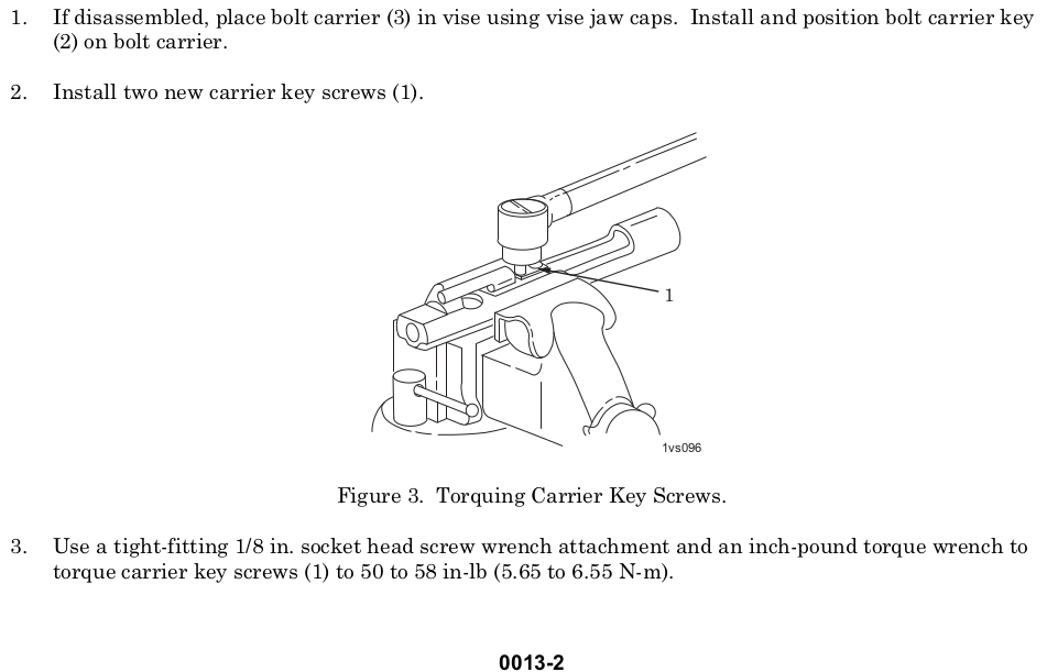
AR Carrier Key Screws 50-58 INCH pounds torque
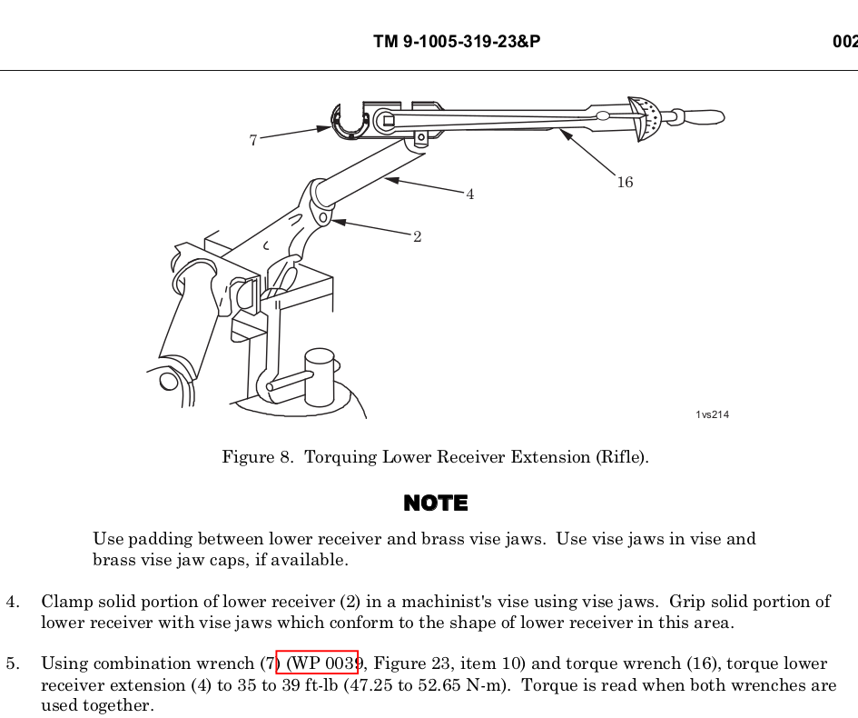
AR Lower Receiver Extension (Buffer Tube/Castle Nut) 40 Ft. lbs for both Rifle and Carbine.
M-LOK Accessories:
For attaching metal accessories to metal hand guards: 35 in/lbs
For attaching polymer or metal accessories to polymer hand guards: 15 in/lbs
For attaching polymer accessories to metal hand guards: 15 in/lbs
The installation torque values are not minimums, they are recommended limits. The nylon patch compound may slightly affect the torque reading if using an in/lb torque wrench.
Using a small hex wrench should prevent over-tightening. Remember that the recoil lugs are doing most of the work, and excessive torque on the nuts is not required
My Comments:
The rest of the items in the research below I could not find in the Army TM, manufacture website or in common reference. Until I can find it, I am going with ‘tight’ and the appropriate thread lockers. ‘Tight’ might be the values listed.
I am not saying that the info below is wrong or bad. I could not readily verify it. The above is what I will use, at the end of the day I am responsible for my decisions and you are responsible for yours.
########### RESEARCH ITEMS BELOW ###########
AR Compensator (Flash hider), 15-20 Ft. Lbs. Torque *1
AR Compensator (Flash hider) *3 (No Torque, timing value)
Army TM Flash Hider
AR Handguard Screws, 20-30 inch pounds torque *1
AR Gas Block Set Screws, 25-30 inch pounds torque *1
AR Barrel Nut, 30 Ft. lbs. Minimum, not to exceed 80 Ft. Lbs. to align the next slot in the barrel nut. *1 *5
AR Barrel Nut, 30 Ft. lbs. *3 (I cant find the 80 Ft. Lbs. In the TM)
Army TM Barrel Nut
AR Carrier Key Screws, 50-58 INCH pounds torque *1 *2 *3
Army TM Gas Key
AR Grip Screw, 15-20 inch pounds torque *1
AR Lower Receiver Extension (Buffer Tube/Castle Nut)
Rifle: 35-39 Ft. Lbs. *1 *3
Army TM Lower Receiver Rifle
Carbine: 38-42 foot pounds *1 *3
Army TM Lower Receiver Carbine
M-LOK Accessories: *4
For attaching metal accessories to metal hand guards: 35 in/lbs
For attaching polymer or metal accessories to polymer hand guards: 15 in/lbs
For attaching polymer accessories to metal hand guards: 15 in/lbs
The installation torque values are not minimums, they are recommended limits. The nylon patch compound may slightly affect the torque reading if using an in/lb torque wrench.
Using a small hex wrench should prevent over-tightening. Remember that the recoil lugs are doing most of the work, and excessive torque on the nuts is not required
All Documents posted on this site are for informational use only. If you make ANY modifications to your Weapons based on this site, you do at your own risk! If done incorrectly, you can render you weapon unsafe and / or unusable.
I wanted a tool to help get the magazine catch pushed out of my M16/AR-15 without scratching or marring the metal. To compresses the spring and make removal of the magazine catch easier.
Looking around I saw AR Magazine Catch tools similar to mine on various web sites for around $10 without shipping. I am frugal and own a 3D printer, I decided to make one.
I know you can use many other things to push it out, such as, but not limited to, pencil, punch, your kids finger….If you have a 3D printer it is a quick and cheap print.
All Documents posted on this site are for informational use only. If you make ANY modifications to your Weapons based on this site, you do at your own risk! If done incorrectly, you can render you weapon unsafe and / or unusable.