Glock Connector polishing notes

Do a basic polish. When that is done put a very slight bevel on the face of the ledge.

Side Drawing and Picture of connector before:

Connector Side Factory Edge Pop Out
Connector Side Factory Edge

Very slightly bevel the face of the ledge.

Connector Side Modified Edge Pop Out
Example Side Modified Edge

All Documents posted on this site are for informational use only. If you make ANY modifications to your Weapons based on this site, you do at your own risk! If done incorrectly, you can render you weapon unsafe and / or unusable.

More HERE: https://viking-armory.com/?page_id=723

Glock Trigger Shoe Modifications

Glock Trigger Shoe Back MeasurementsGlock Trigger Shoe Screw Measurements Front

The above are average measurements. It is polymer, it moves so you will not get consistent measurements. They are mass produced and can vary in size between batch runs. The trigger I had at the time had the above measurements. Yours might vary. “A” was my distance to the center of the trigger bar slot.

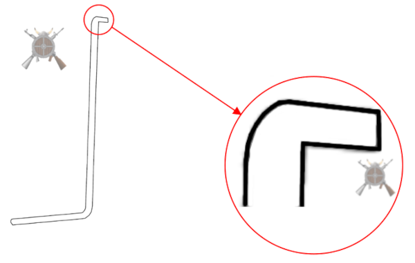
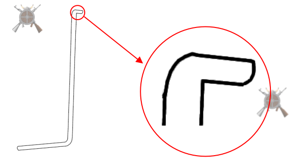
We want to get the screw hole centered in front of the trigger bar slot (A) left to right and at the height of the front curve.

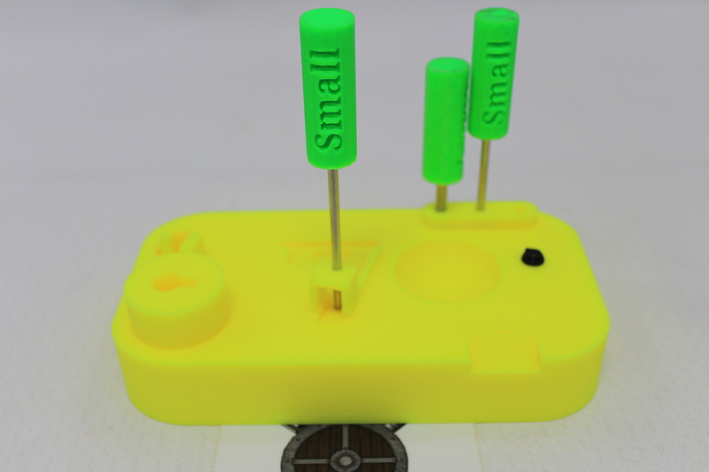
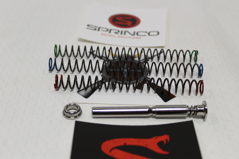
You are going to need Standard Trigger:

 2 - 56 3/16 long stainless steel socket set screw 
 2 - 56 3/8 long stainless steel socket set screw for trigger bar
 .035 Allen Wrench
 #50 drill bit
 2 - 56 tapered tap

You are going to need Performance Trigger:

 2 - 56 3/16 long stainless steel socket set screw
 2 - 56 3/8 long stainless steel socket set screw for trigger bar
 .035 Allen Wrench
 #50 drill bit
 2 - 56 tapered tap


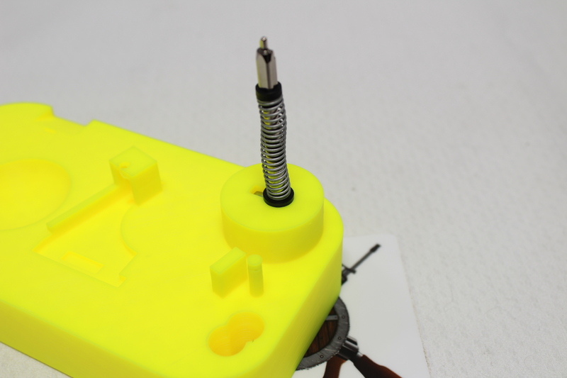
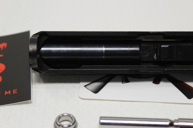
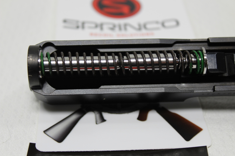
Using the #50 drill bit, drill a hole 9 mm down and center of the trigger bar slot. Make sure it is straight. I use my Dremel Drill press to do this. Slowly work the 2 – 56 tap through it.
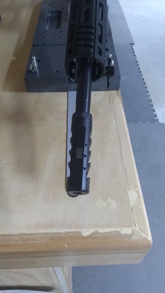
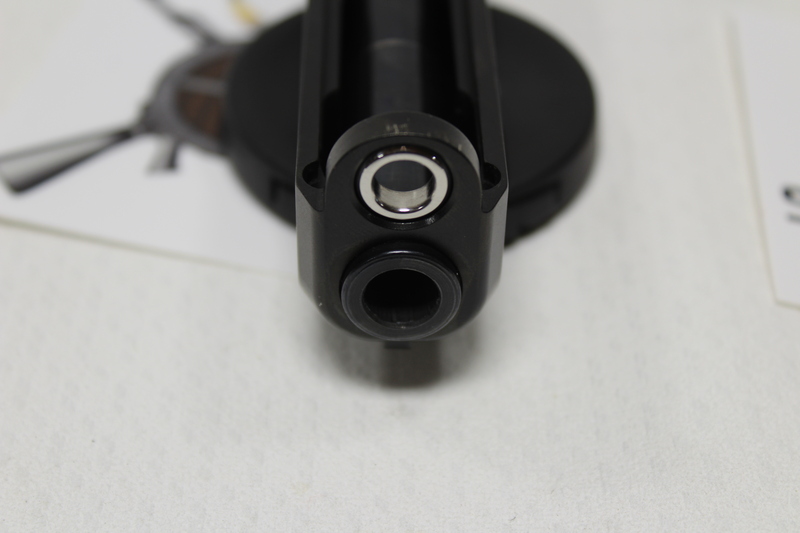
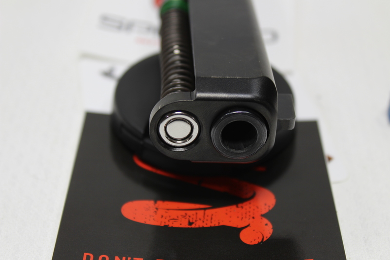
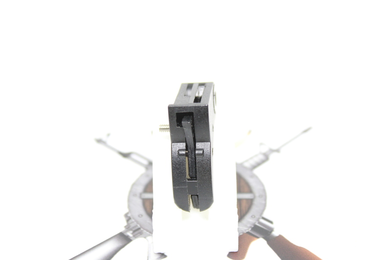
Front Shot:

Glock Trigger Front Set Screw

Looks pretty centered:

Glock Trigger Back Set Screw

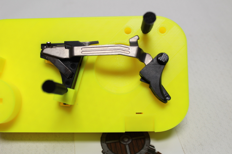
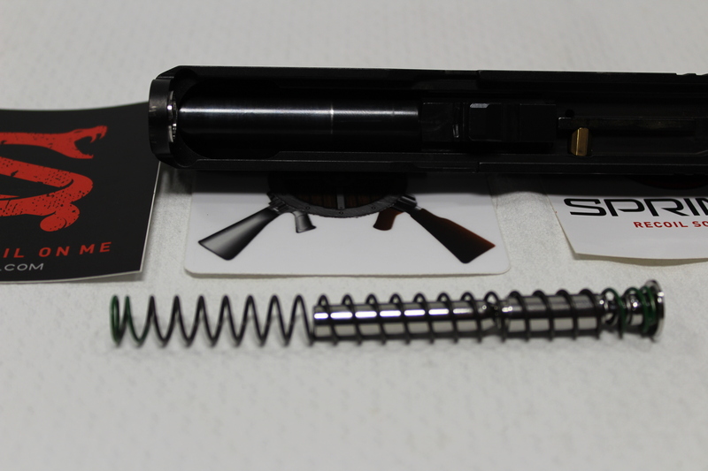
While I am at it, I drilled and tapped the safety and trigger bar holes with the above tools and threaded in 2 – 56 x 3/8” set screws

Glock Trigger Safety and Trigger Bar Screws

Once I am confident that everything is setup correctly, I will seal the deal with Loctite 425

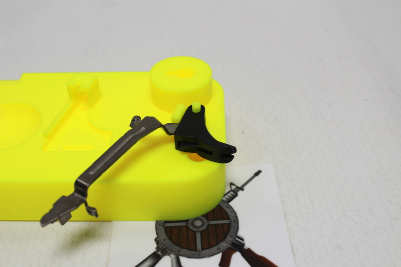
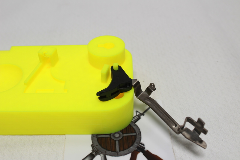
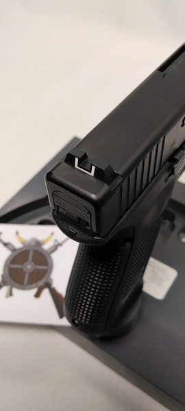
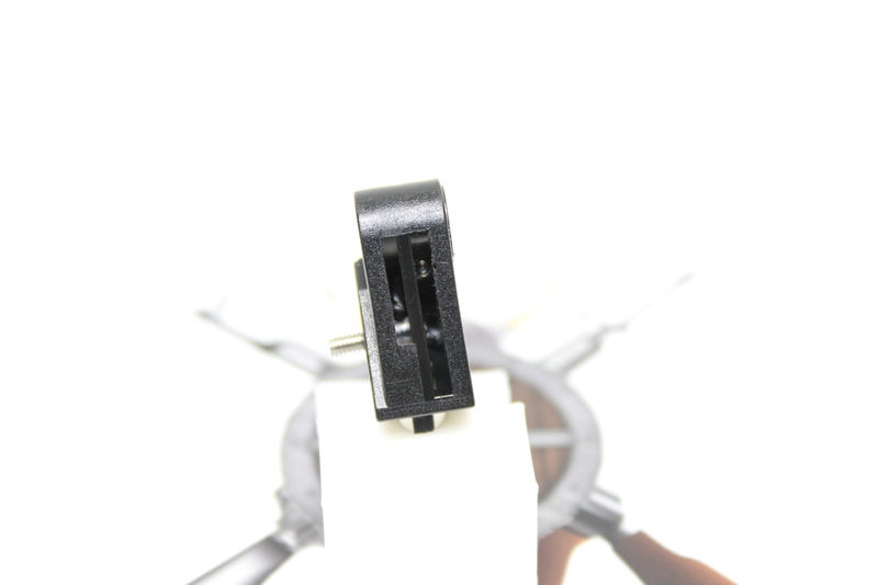
I modified the safety on this trigger as well

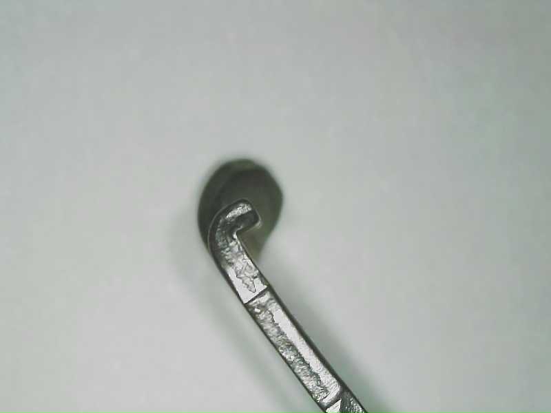
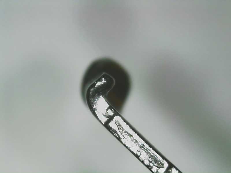
Here is what the trigger safety looks like unmodified:

Glock Trigger Sfty Front

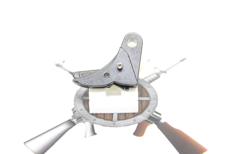
There are 4 different cuts I am going to try.

Trigger Sfty Front Cut Options

Never cut off more than shown in the last example.

Here is the start of my testing:

Glock Trigger Safety Modification

Hit us up with comments or requests

All Documents posted on this site are for informational use only. If you make ANY modifications to your Weapons based on this site, you do at your own risk! If done incorrectly, you can render you weapon unsafe and / or unusable.

More HERE: https://viking-armory.com/?page_id=723

GlockSmith Block

I wanted to create a block that Glock Armorers could use to perform Glock-Smithing tasks regardless of Glock model.

GlockSmith Block Naked 2

GlockSmith Block Naked Showing New PinsSo far it has spots for:

– Trigger Shoe Removal and Install

GlockSmith Block Trigger Shoe Pin Install GlockSmith Block Trigger Shoe Pin Remove

– Connector Adjustments

GlockSmith Block Connector Adjuster

– Trigger Jig

GlockSmith Block Trigger Jig

Showing the new pins:

GlockSmith Block Trigger Jig New Pin
GlockSmith Block Trigger Jig with new pin

– Firing Pin Spring and Cup(s) replacement

GlockSmith Block Firing Pin

It has been working out pretty good for me. If you have suggestions or ideas hit me up using the info below.

Download HERE

Hit us up with comments or requests

All Documents posted on this site are for informational use only. If you make ANY modifications to your Weapons based on this site, you do at your own risk! If done incorrectly, you can render you weapon unsafe and / or unusable.

More HERE: https://viking-armory.com/?page_id=723

Foredom Yoke

I wanted to make a Yoke assembly for my Foredom motor, something like this one.

I had this big bearing from a previous project. This led me to create 2 versions:

Big Bearing:

Foredom Yoke Large Bearing Foredom Yoke Large Bearing Base

And a standard 608 Skate Board Bearing  version:

Foredom Yoke Skate Bearing

The insert works for both:

Foredom Yoke Screw Insert

Looks and works pretty good! I have been using the large bearing version for around 6 months with no issue. I am not a heavy Foredom user, it is a tool in my tool box.

Foredom Yoke Complete

Download HERE

Hit us up with comments or requests

Part Polishing Notes

Surface:

Glass Plate as a work Surface, Anything hard and flat

Backing:

Leather

Thin Foam

Straight on the glass surface:

320 takes the longest

400

600

800

On glass surface with foam under sandpaper:

1000

1500

2000

2500

Worksharp:

6000 purple belt

Cordless Dremel;

14000 grit diamond compound

Notes:

It will look like a rainbow, seeing copper and nickle is normal

All Documents posted on this site are for informational use only. If you make ANY modifications to your Weapons based on this site, you do at your own risk! If done incorrectly, you can render you weapon unsafe and / or unusable.

More HERE: https://viking-armory.com/?page_id=723

A bore guide with holding pin for AR-10 .308

I have been using a bore guide on my AR15s for several years. I recently purchased a .308 AR10 and set out to make one for it.

I liked @ThomasXIII threaded middle shown HERE  So I made mine with the same threaded center.

AR-10 / 308 Bore Guide and Link Pin Family Shot

I also made a hold down pin to keep everything in place.

AR-10 / 308 Bore Guide and Link Pin All Together

Fits snug and have had no issues passing my cleaning rod with swabs.

AR-10 /308 Bore Guide and Link Pin Working
AR-10 / 308 Bore Guide and Link Pin installed

Hit us up with comments or requests

All Documents posted on this site are for informational use only. If you make ANY modifications to your Weapons based on this site, you do at your own risk! If done incorrectly, you can render you weapon unsafe and / or unusable.

More HERE: https://viking-armory.com/?page_id=723

Safety Plunger De-Bur and Polish

Glock pistols are mass produced using stamped parts. That is not a bad thing, just the way it is. Because of that, a part will sneak in with a less than desirable finish. I am of the belief that you should inspect all you parts for defects and burrs.

In this case, I found a bur on the safety plunger.

Glock Sfty Plunger burr pointed out

I filed down the burr with a small file, being careful not to remove to much material.

Glock Sfty Plunger burr filed down

When it met my stringent standards I polished it up:

Glock Sfty Plunger Polished side
Glock Sfty Plunger Polished Top

Dropped it back in, runs like a champ!

Hit us up with comments or requests

All Documents posted on this site are for informational use only. If you make ANY modifications to your Weapons based on this site, you do at your own risk! If done incorrectly, you can render you weapon unsafe and / or unusable.

More HERE: https://viking-armory.com/?page_id=723

Compensator Install

A compensator is a muzzle device designed to reduce muzzle rise. A compensator will “compensate” for a firearm muzzle’s rise after you fire a shot, this directly affects follow-up shots because they help you recover your sight picture by shooting flatter.

There are many articles about what is best out there. We leave that up to you.

You want to make sure your compensator is timed correctly. Timing is simply insuring that the ports are properly positioned. With the proper tools and hardware provided with your device I can get you timed and aligned correctly.

Here are a couple Shots of what I do:

AR compensator Service 1
AR compensator Service
AR compensator Service 2
AR compensator Service

Hit us up with comments or requests

All Documents posted on this site are for informational use only. If you make ANY modifications to your Weapons based on this site, you do at your own risk! If done incorrectly, you can render you weapon unsafe and / or unusable.

More HERE: https://viking-armory.com/?page_id=723

Glock Sight Install

We all know the factory Glock sights are notoriously poor, so let me replace them! I take a lot of care to make sure the sights on your pistol are installed and aligned correctly. I have a very nice sight pusher tool that drifts the sights on and off without the need of a punch or hammer. Using such a tool protects tritium vials from breaking, prevents marring of the slide, and the sights.

Here is a shot of a Glock 19 I did:

Factory Front Sight:

Glock Factory Front Sight

Factory Rear Sight:

Glock Factory Rear Sight

Sights getting installed:

Glcock Sights Getting installed
New Glock Rear Glock Sights Installed

New front sight:

New Glock Sights installed

Hit us up with comments or requests

All Documents posted on this site are for informational use only. If you make ANY modifications to your Weapons based on this site, you do at your own risk! If done incorrectly, you can render you weapon unsafe and / or unusable.

More HERE: https://viking-armory.com/?page_id=723

SpringCO Recoil Management System

I just picked up the Recoil Management System, Versatility Kit from the great folks at SpringCO for my Glock 19 Gen 5. I wanted to show what I did to get it installed. It was pretty straight forward and easy to do.

Here are the parts that came in the package.

SpringCO Glock Recoil Management System Whats Included

I am going to install the Green 13# spring. As this is a non-captured setup I will be trying the 15 and 17 pound springs in the near future and keeping the one I like best and works best for my situation.

SpringCO Glock Recoil Management System what I am installing

Remove the existing recoil spring

SpringCO Glock Recoil Management System remove the old

Make sure the Guide Rod Forward Bushing goes in with the small section forward as show in the picture:

Make sure the Guide Rod Forward Bushing goes in with the small section forward
SpringCO Glock Recoil Management System Bushing direction

Here are a couple more shots of what it should look like:

SpringCO Glock Recoil Management System Bushing Direction 2

Front:

SpringCO Glock Recoil Management System Bushing front view
SpringCO Glock Recoil Management System Bushing Direction front view

Slide the spring you want to use on the guide rod:

SpringCO Glock Recoil Management System Bushing slide on the spring

Place the spring in the Guide Rod Forward Bushing and carefully push in place. The guide rod will fit into the hole in the bushing.

The guide rod will fit into the hole in the bushing.

After everything is lined up everything will fit like the original.

After everything is lined up everything will fit like the original.

Front shot of how the bushing should look:

Front shot of how the bushing should look
SpringCO Glock Recoil Front shot of how the bushing should look

There are several videos that explain what is going on with the system when it is installed. I wanted to share my experience getting it installed.

REF:

https://www.sprinco.com/springs.html

Glock® 19/23/32/45 Chrome Silicon Moly Plated Cryogenic Processed Recoil Spring – 13# (Color Coded GREEN)

Glock® 19/23/32/45 Chrome Silicon Moly Plated Cryogenic Processed Recoil Spring – 15# (Color Coded BLUE)

Glock® 19/23/32/45 Chrome Silicon Moly Plated Cryogenic Processed Recoil Spring – 18# (Color Coded RED)

Sprinco USA recoil reducer Review https://www.youtube.com/watch?v=gEtd79ss4Vc

Hit us up with comments or questions

All Documents posted on this site are for informational use only. If you make ANY modifications to your Weapons based on this site, you do at your own risk! If done incorrectly, you can render you weapon unsafe and / or unusable.

More HERE: https://viking-armory.com/?page_id=723

Copy link
URL has been copied successfully!
error: Content is protected !!