I want to give a shout out to DOODLE REPAIR of Rockton, IL for helping us fix some issues with our old blocks and testing some new ones that will be coming out soon!
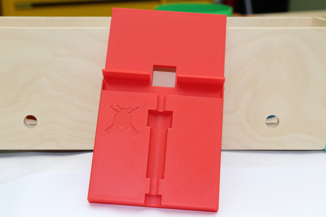
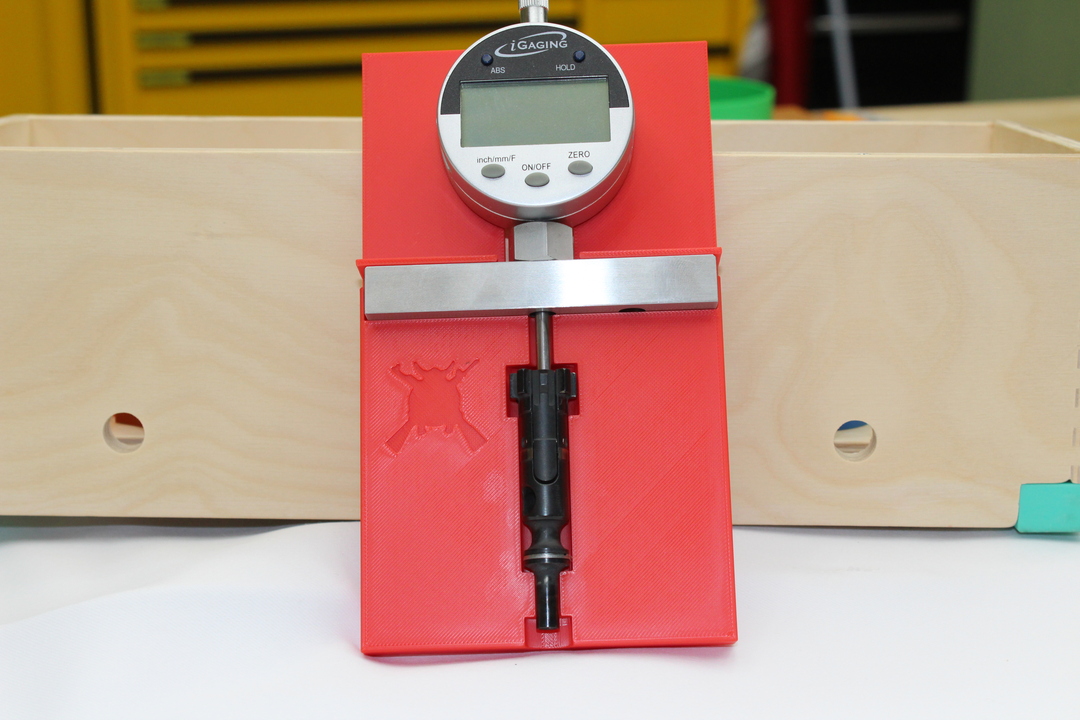
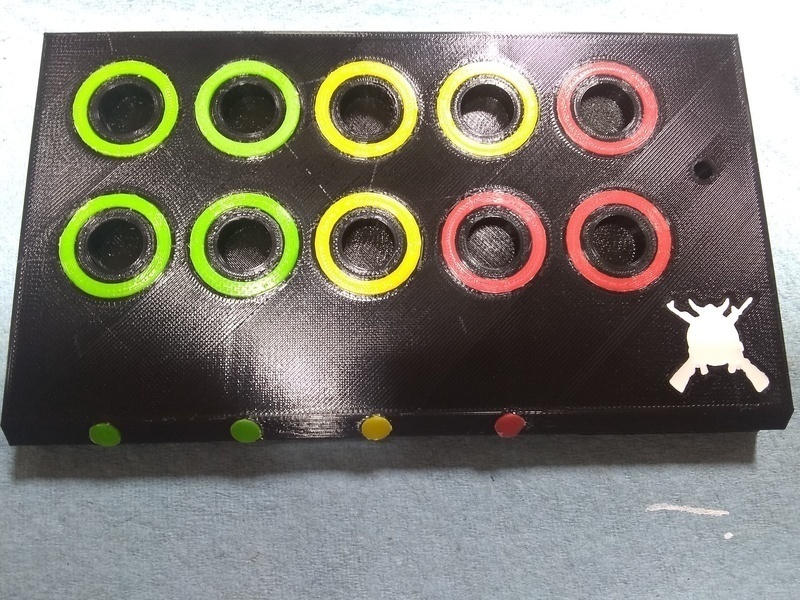
All our vise blocks are printed with American Made PCTG with at least 50% infill to give you the strength to do what you need to do. They will hold securely in your vise, including 4 inch vises and lock in just like a magazine will. This allows you to have your hands free to work on the task in front of you. Keeps weapons secure for safe cleaning, assembly and repair.
If you want to customize your blocks let us know and we can use your logo, change color, pretty much anything you want. Some colors might not be available with our American made PCTG, We will work with you to find a quality solution. There might be an additional cost depending on what you want done.
If there is something you don’t see us offering, let us know and we will work with you to to make it.
Right now we offer vise blocks for:
All Glocks including the new Gen 6
1911
AR-15
AR-10 .308
AK-47
AK-74
More on the way!
Get yours here!